
PMI foam core
Rigid, closed-cell structural foam for high-performance sandwich composite concepts.
CoreMatrix Materials / PMI structural foam core
High-performance PMI foam cores, precision CNC machining, and custom composite core solutions for aerospace, UAV, radome, and advanced composite applications.
01
PMI core
02
CNC shaping
03
Composite process
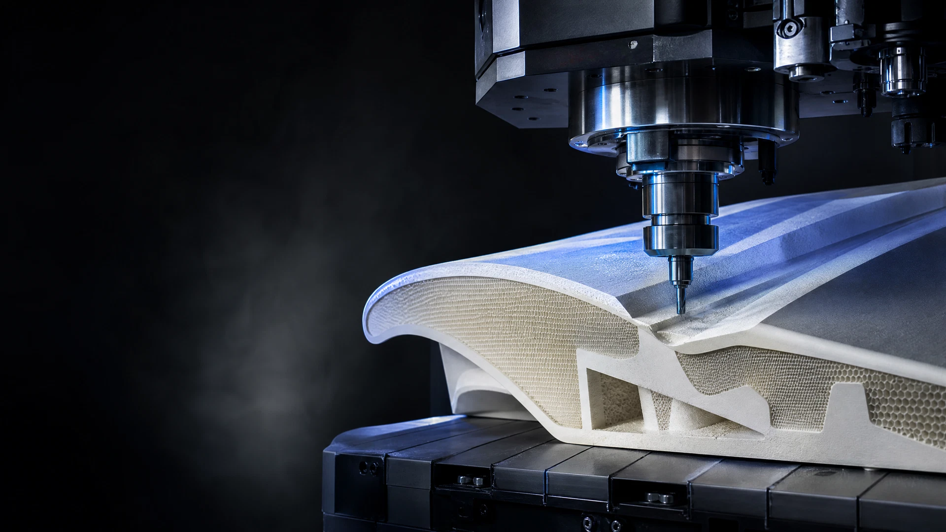
PMI product architecture
Select the PMI core around the finished structure: material form, anticipated geometry, manufacturing route, and the evidence required for a confident technical review.
Rigid, closed-cell structural foam for high-performance sandwich composite concepts.
A source-catalogue pathway for integrated, complex foam-core geometries.
Milling, routing, drilling, grooving, contouring, and custom 3D core forms.
PMI core context for CFRP structures, curing routes, and component manufacture.
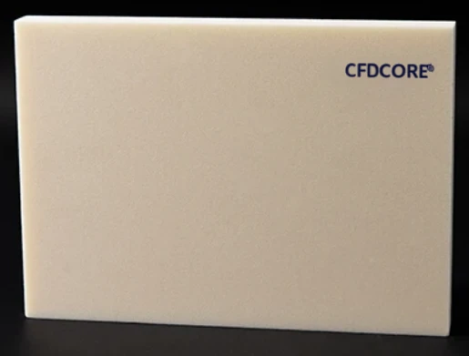
PMI foam core
Frame the PMI core around the decisions that define the finished part: core form, process route, geometry, and the intended sandwich structure. The technical review begins with the component, not a generic material claim.
Rigid, closed-cell PMI foam core positioning
CNC, hot-pressing, and bonding as core preparation pathways
Autoclave, vacuum bagging, RTM, VARTM, VARI, and HP-RTM process context
Core preparation route
Trace a clear route from core selection through mold-forming or CNC preparation to the downstream composite manufacturing process.
CAD review
Material selection
Core forming
CNC machining
Composite process
Inspection & export
Share STEP, STP, DXF, DWG, STL, or a PDF drawing to start a review of foam form, core geometry, CNC preparation, and composite process context.
View CNC processesComposite application context
Begin with the end-use structure, then establish the core’s role, its geometry, and the appropriate composite manufacturing route.
Composite material solutions
Bring the CFRP reinforcement context, PMI core form, laminate logic, and structural objective into one focused technical pathway.
Organize the reinforcement, core, laminate logic, and structural objective in the same enquiry.
Review integral features, complex geometry, and the suitable preparation route before production.
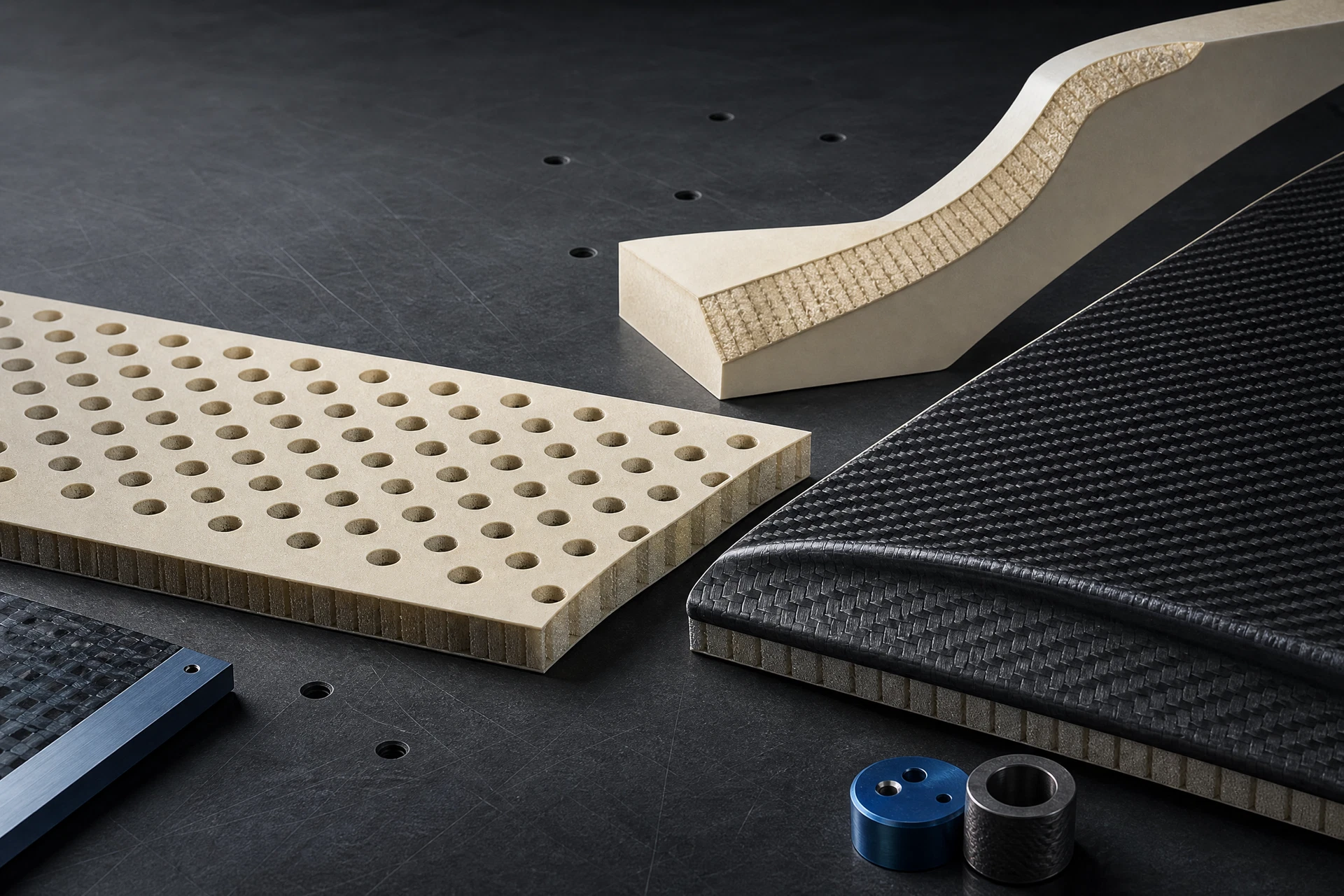
Technical resource center
Guide 01
Structural form, closed-cell core context, and core terminology.
Read guideGuide 02
Autoclave, vacuum bagging, RTM, VARTM, VARI, and HP-RTM context.
Read guideGuide 03
Core shaping, grooves, drilling, contours, data preparation, and inspection.
Read guide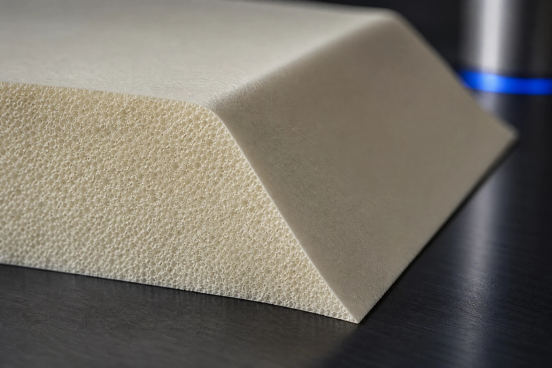
Engineering field notes
The content library is built around the decisions that repeatedly shape PMI core projects: how the sandwich is constructed, which geometry is controlled by CAD, what process follows core preparation, where documentation is needed, and what should be included before a quotation is requested.
Related questions
These questions link the homepage to deeper technical pages. They are designed to help a design, sourcing or manufacturing team move from a broad PMI search to a structured project brief.
Begin with the component, skins, intended geometry, process and the documentation required for the proposed grade.
Use a drawing-led review when contours, channels, holes, pockets, interfaces or other controlled features connect the core to the composite component.
Bring the geometry, construction, manufacturing context and RF-data request into one documented project review.
Request the technical document against the actual component and process; generic web values should not replace applicable grade data.
Compare the project’s grade documentation, process, geometry and commercial context rather than relying on a generic winner claim.
Technical action surface
Start a focused discussion with PMI core type, intended component, composite process, and available drawing format.
Material and process gallery
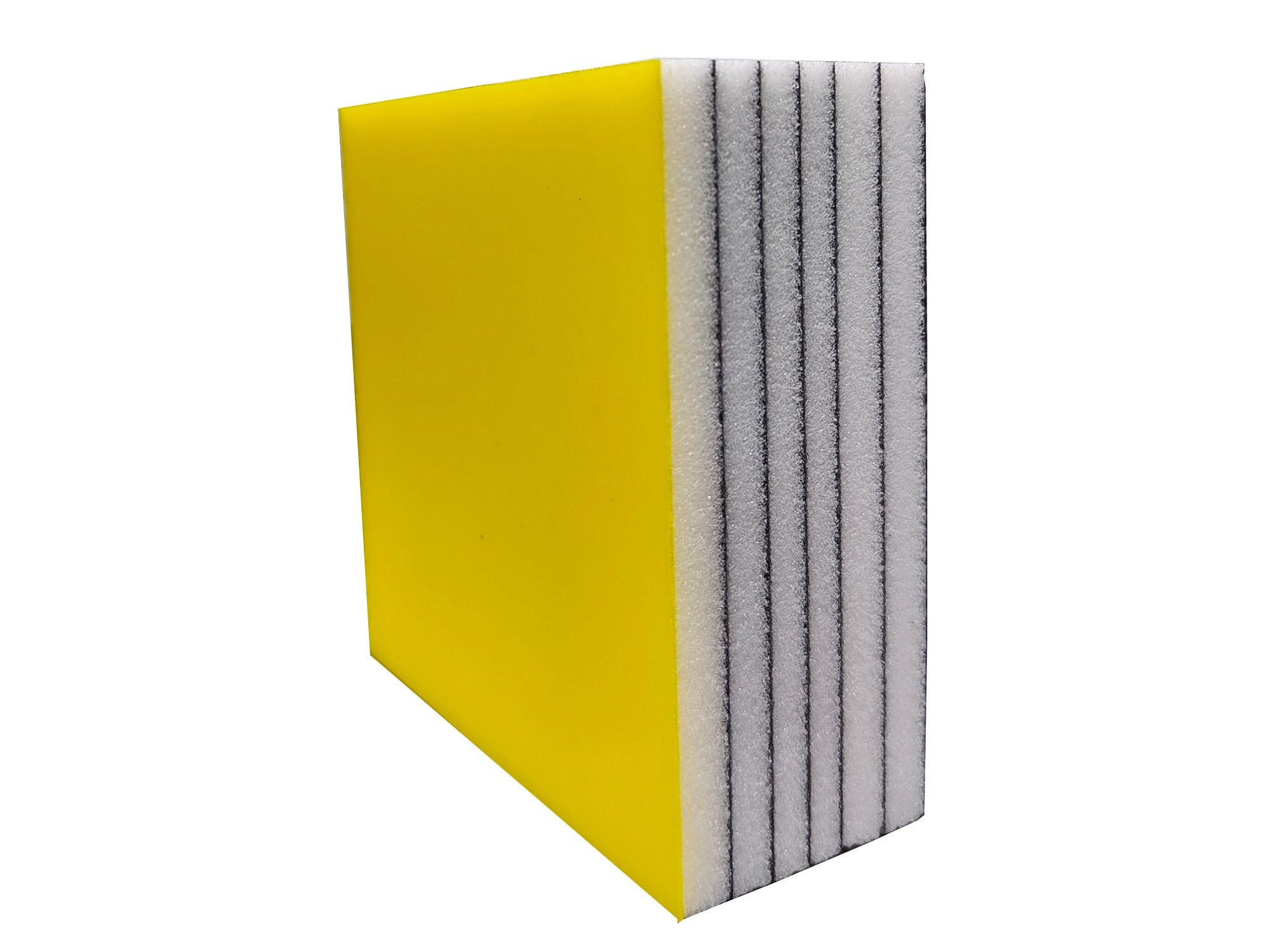
Use the gallery to move from a visible PMI form or manufacturing question to the corresponding product, CNC, application, quality or RFQ pathway. Every image is representative project context; it does not replace a confirmed project specification.
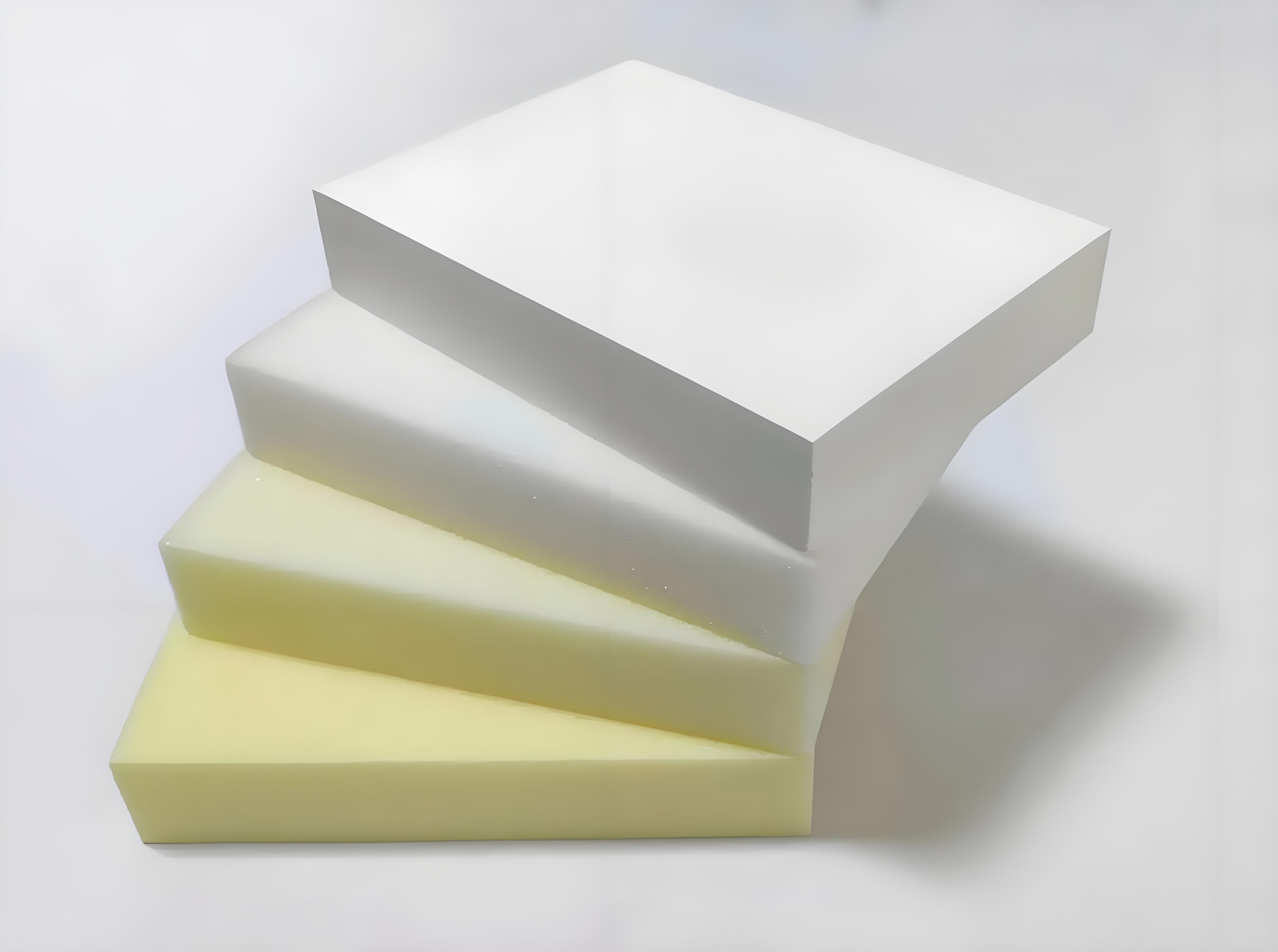
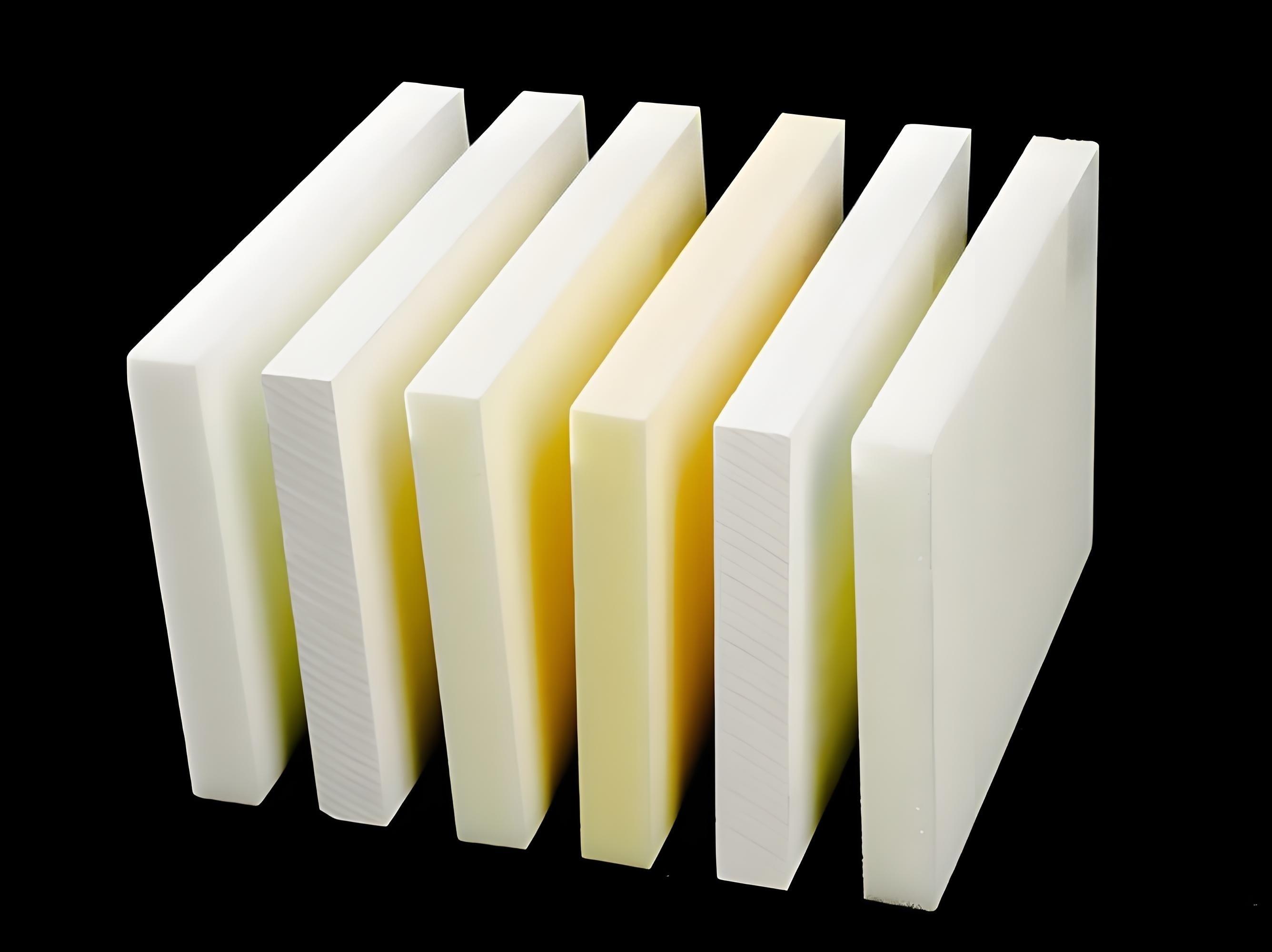
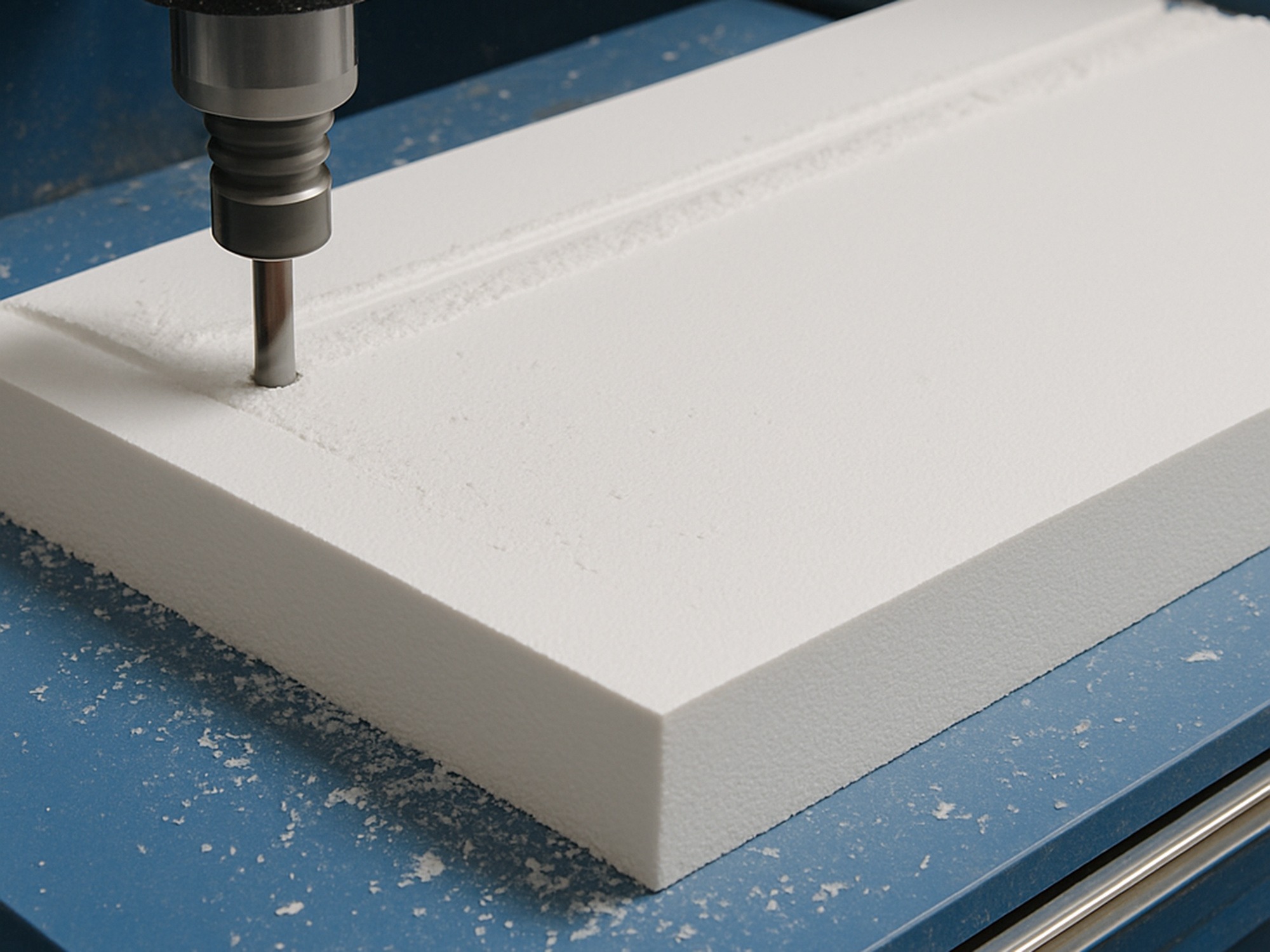
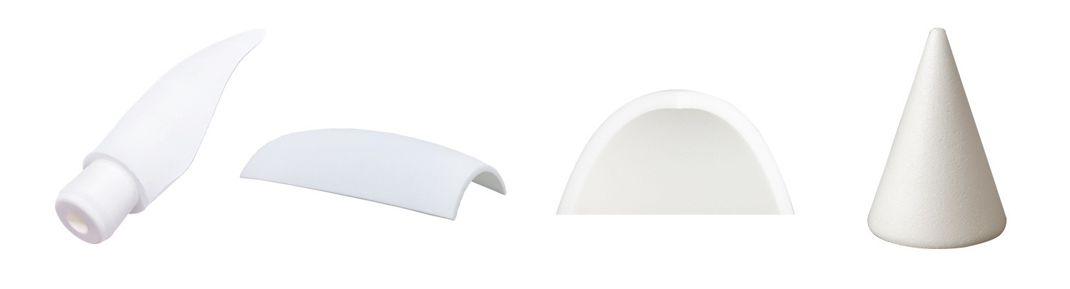
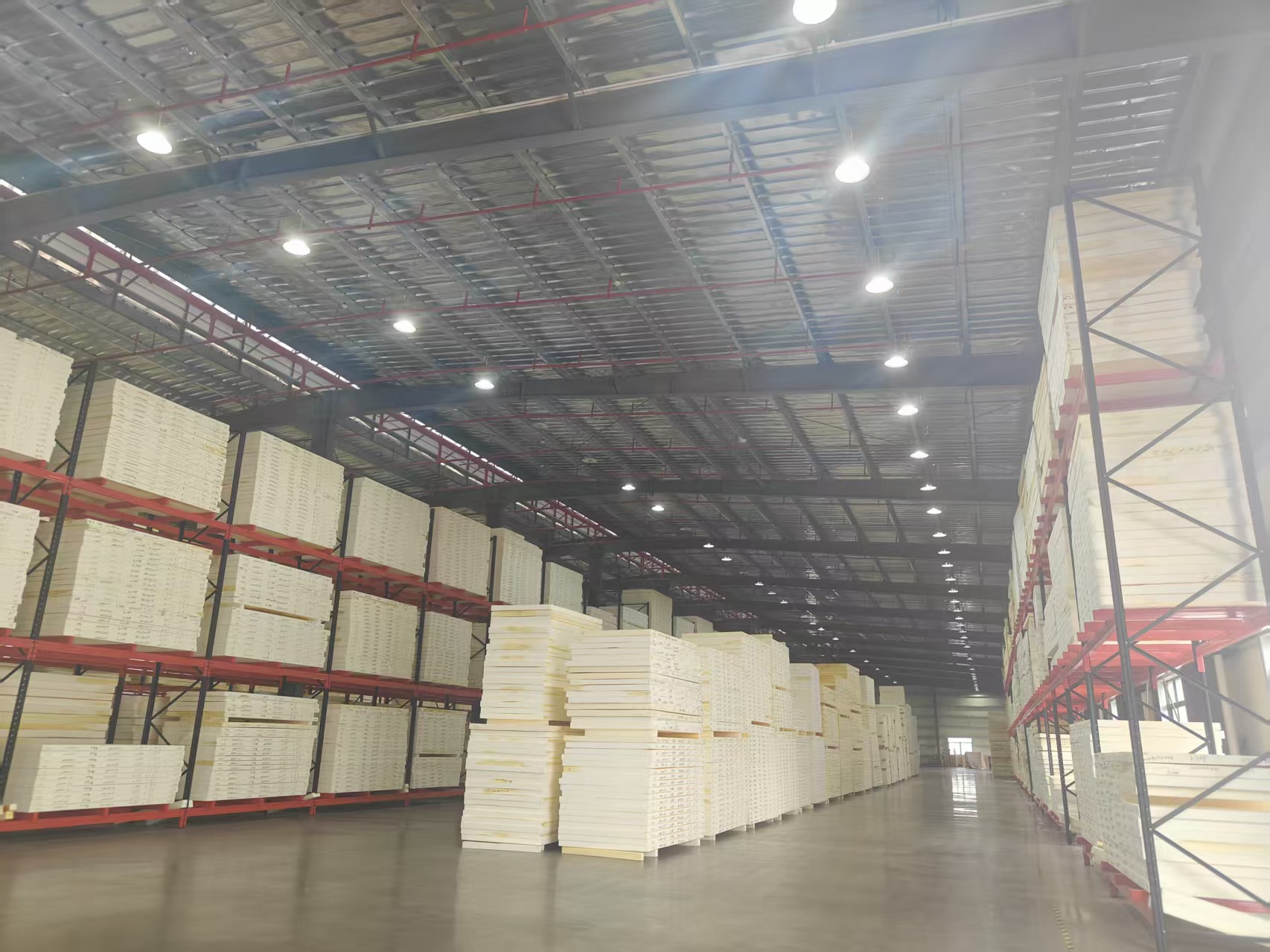
Production field records
These field photographs document representative CNC preparation and finished-core handling. They support a drawing-led discussion of geometry, feature sequence, packing needs and the handoff to the next composite operation; they do not replace a project-specific inspection or acceptance plan.
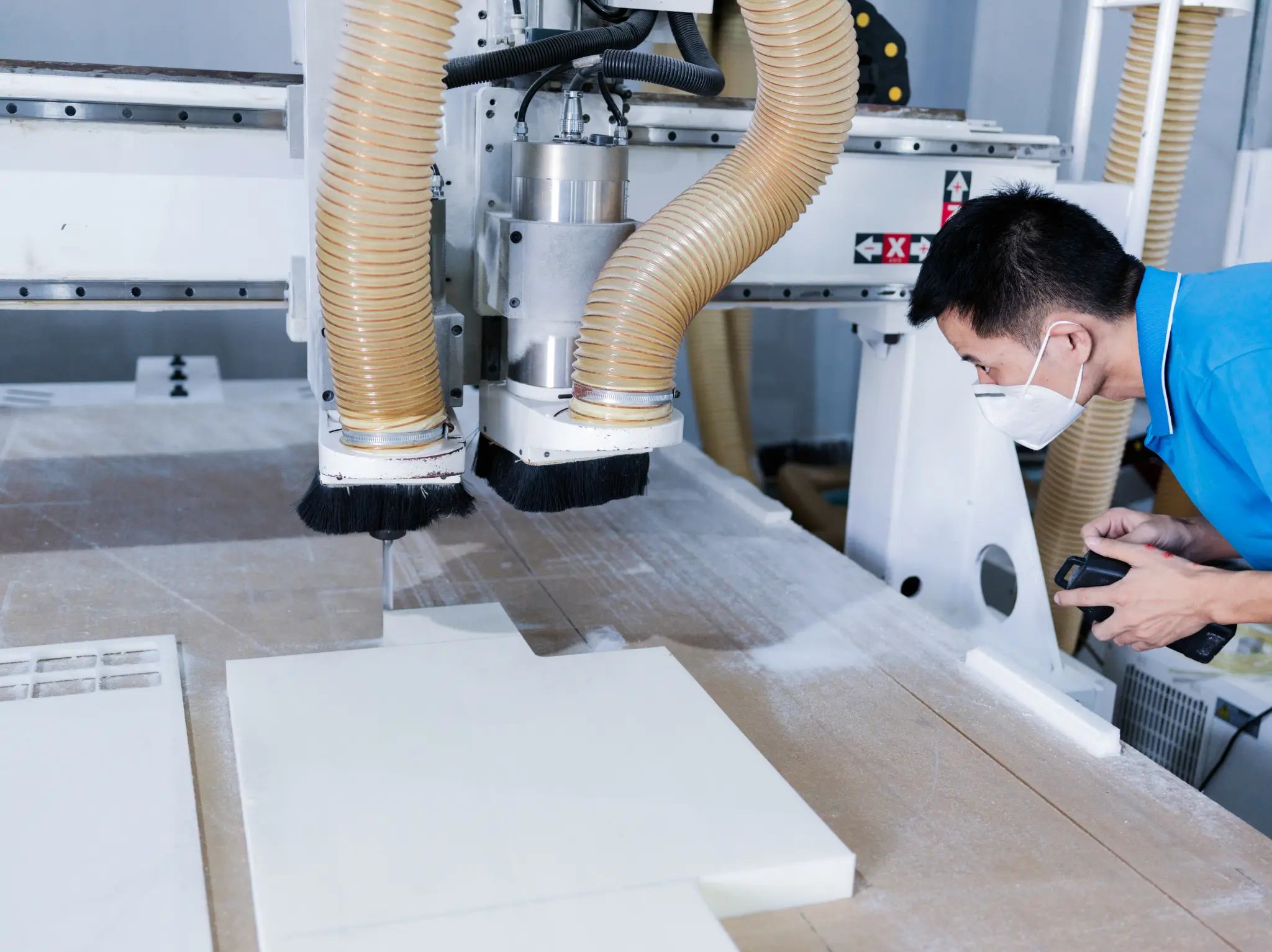
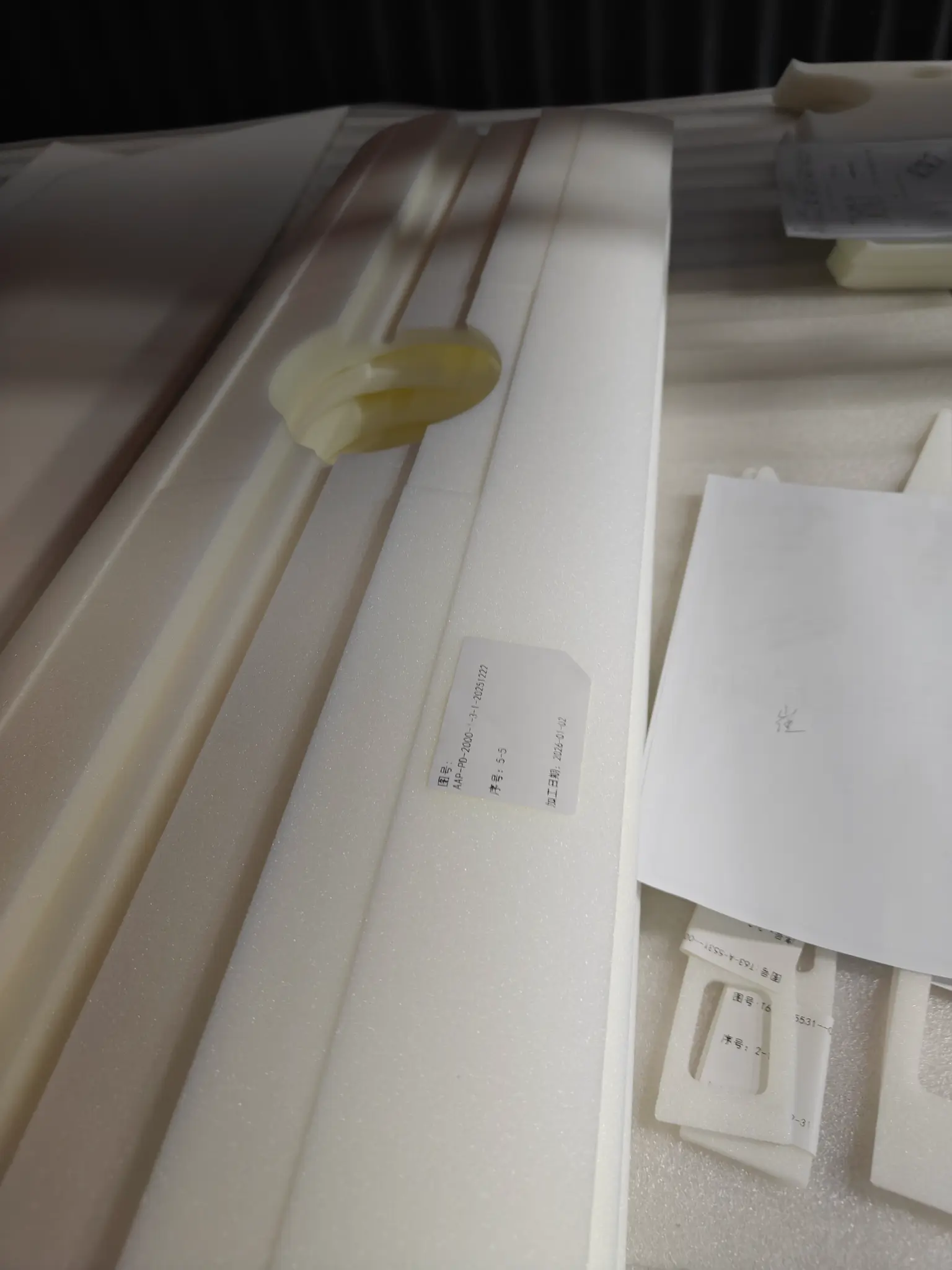
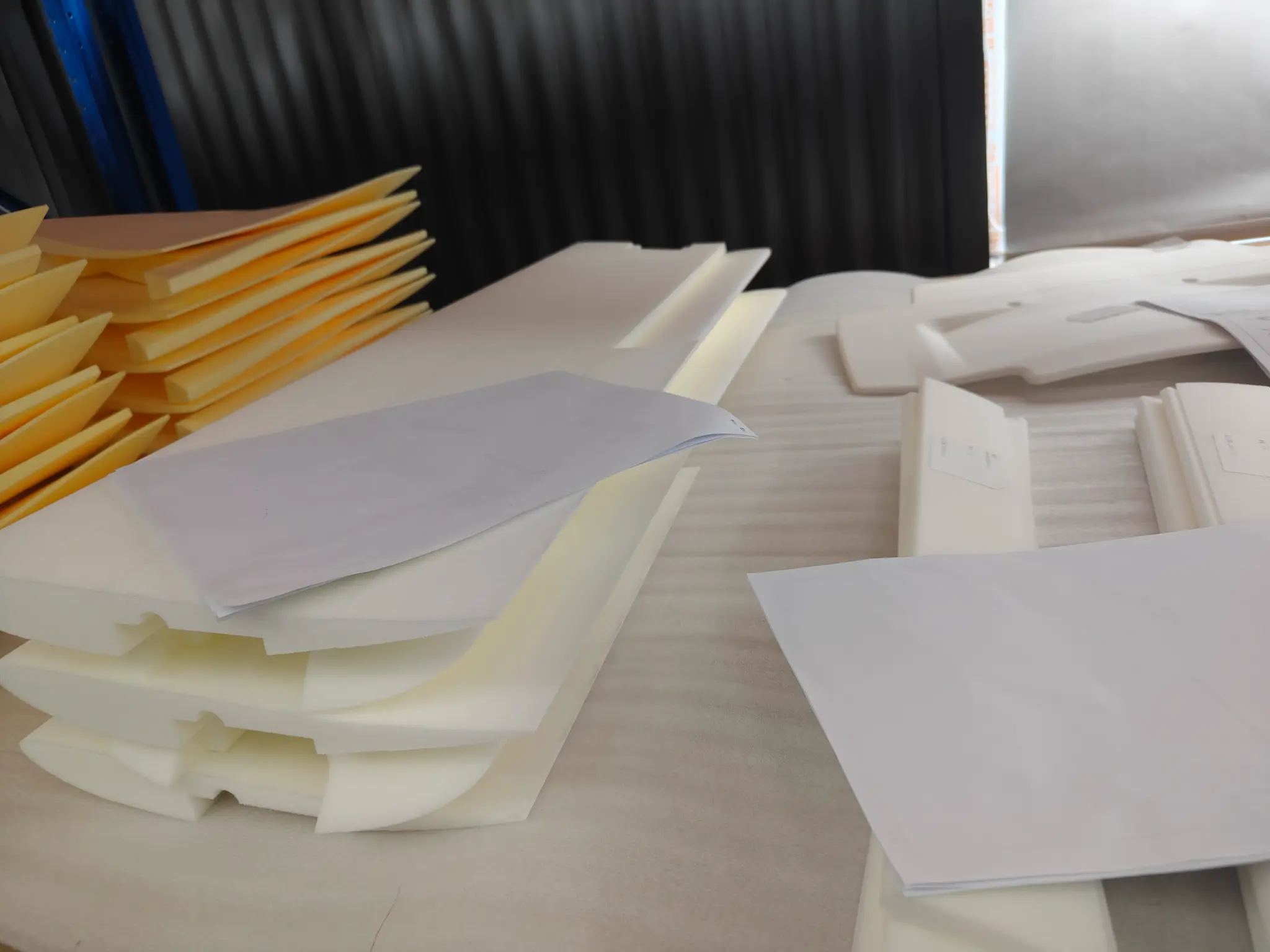
Each image is presented as project context, with the scope of material data, geometry, inspection and commercial commitments kept separate until they are confirmed for the actual order.
Review CNC workflow