
PMI foam CNC machining
CNC processing designed around composite foam core geometry.
The company’s current product information identifies standard CNC equipment, hot-pressing, and adhesive bonding as routes for PMI core preparation. This page turns those capabilities into a project-led machining workflow.
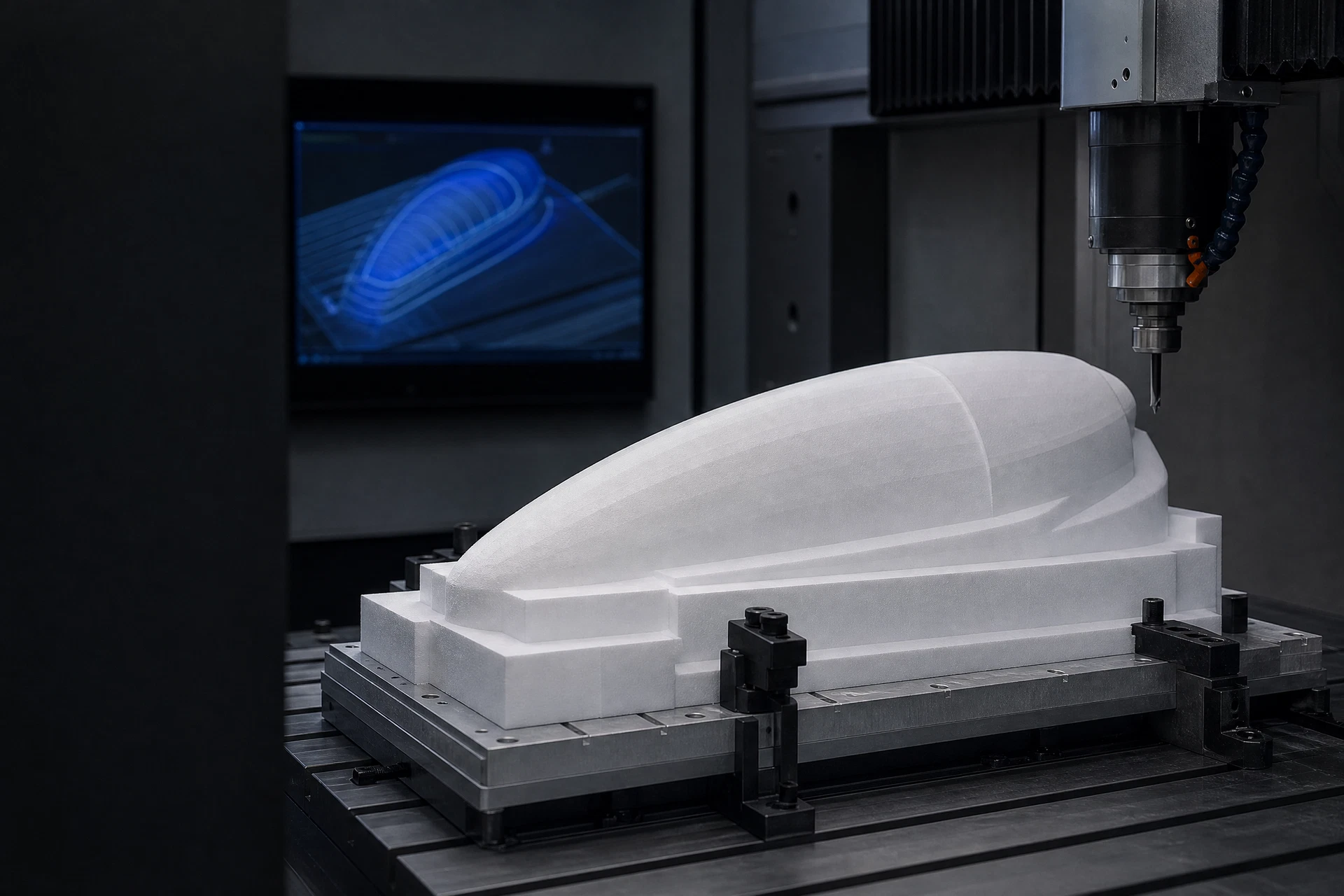
What we machine
Features that move a flat foam sheet toward a finished core.
The right sequence depends on the part, data supplied, and intended downstream composite process. Final details remain drawing-led.
CNC milling
A process route selected around PMI foam form, geometry, and the intended component outcome.
CNC routing
A process route selected around PMI foam form, geometry, and the intended component outcome.
CNC drilling
A process route selected around PMI foam form, geometry, and the intended component outcome.
CNC grooving
A process route selected around PMI foam form, geometry, and the intended component outcome.
3D contouring
A process route selected around PMI foam form, geometry, and the intended component outcome.
Custom shaping
A process route selected around PMI foam form, geometry, and the intended component outcome.
Machining trace
A drawing-led process, recorded as a sequence.
Input review
Toolpath logic
Core machining
Feature inspection
Packing handoff
Input formats
Bring the geometry you have.
Files support an initial review of foam form, machining strategy, feature feasibility, and any relevant downstream composite route.
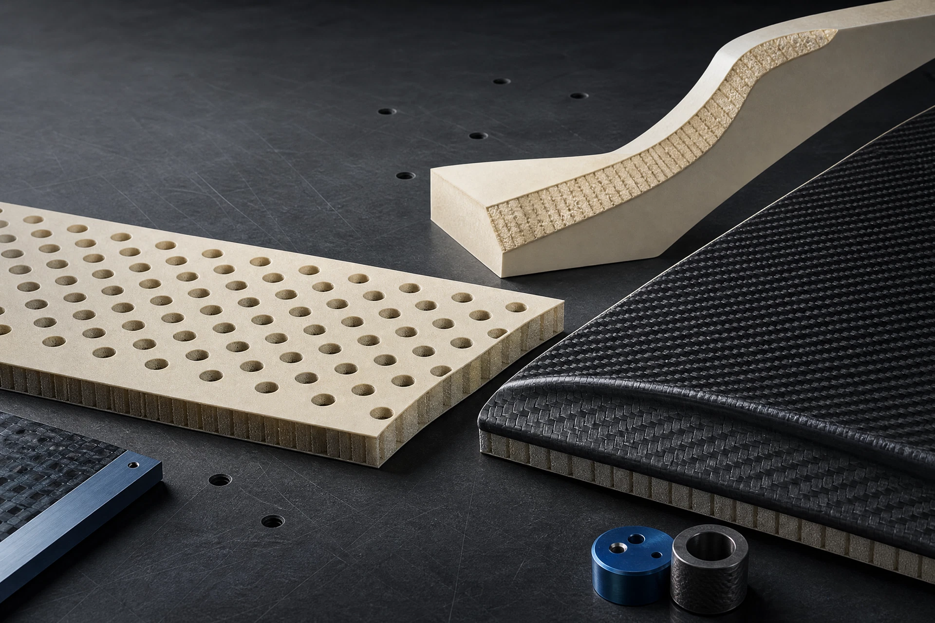
Technical action surface
Send a drawing. Start with the material.
Start a focused discussion with PMI core type, intended component, composite process, and available drawing format.
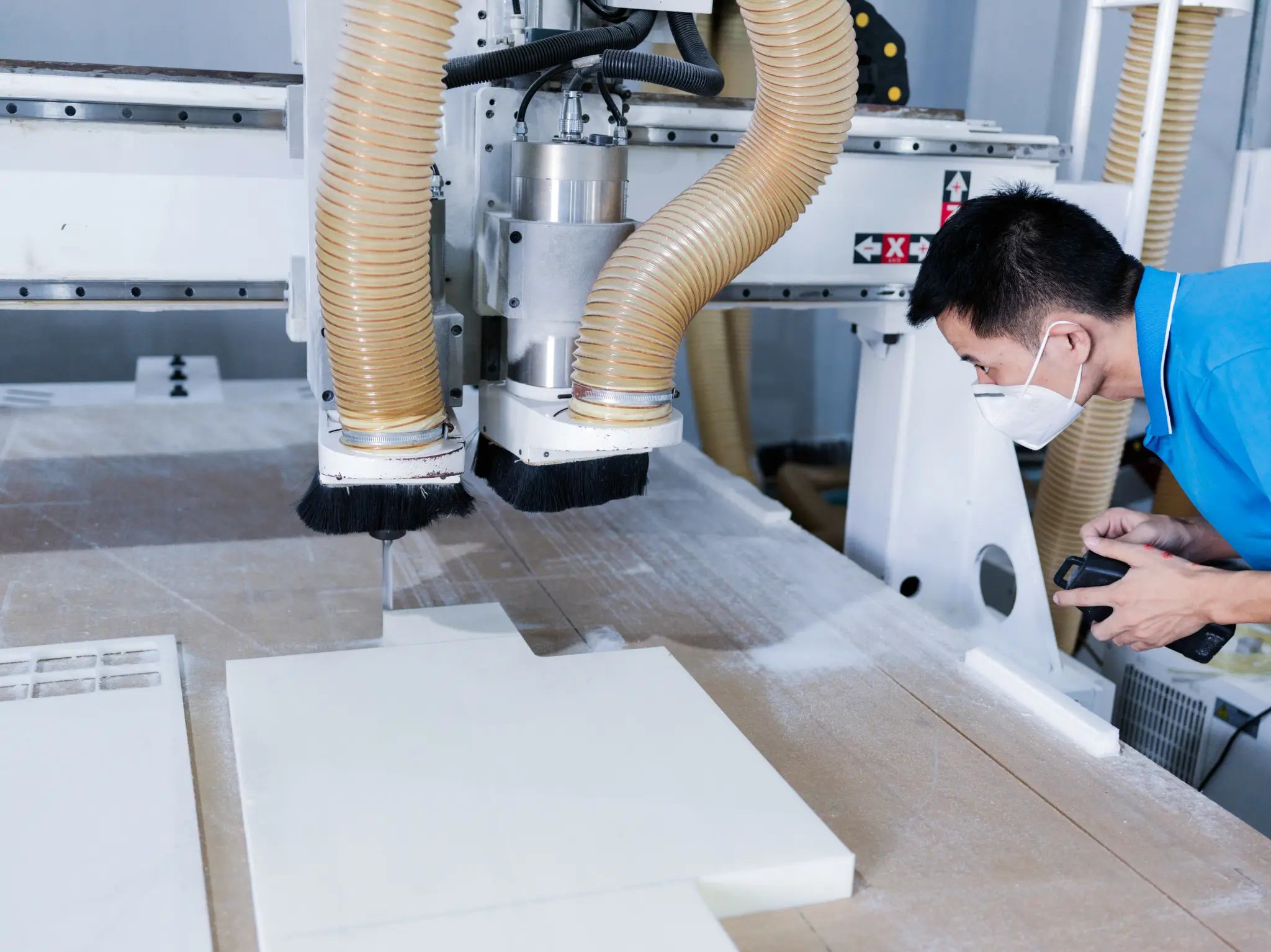
CNC process record
Move from drawing review to a protected composite-ready core handoff.
The main CNC page should show the manufacturing conversation in sequence: a controlled model, appropriate starting form, defined features, inspection references and protected packing. Images document representative process context; they do not replace a project-specific manufacturing plan.
- 01Review STEP, STP, IGES, STL, DXF, DWG or PDF files and the controlling revision
- 02Plan milling, routing, drilling, grooving, pocketing or contours from the actual core geometry
- 03Define inspection, identification, feature protection, packing and export handoff for the order

Process and handoff evidence
Prepared components / identification / handoff context. Images are representative project context and do not independently establish a certified process, finished-part result, material availability or named customer case.
CNC machining evidence
A visible process record, connected to the controlled drawing.
The machining photograph shows a production context with extraction and a prepared foam workpiece. For a real programme, the controlling CAD revision, core form, feature references, inspection points and downstream composite sequence should be reviewed together before a machining route is released.
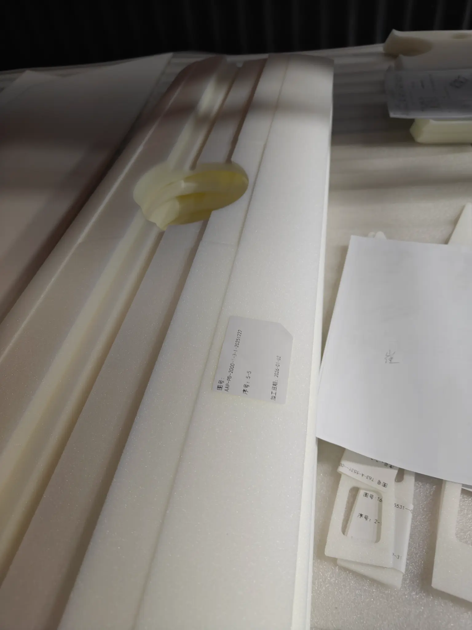
Each image is presented as project context, with the scope of material data, geometry, inspection and commercial commitments kept separate until they are confirmed for the actual order.
Upload a CAD drawing