
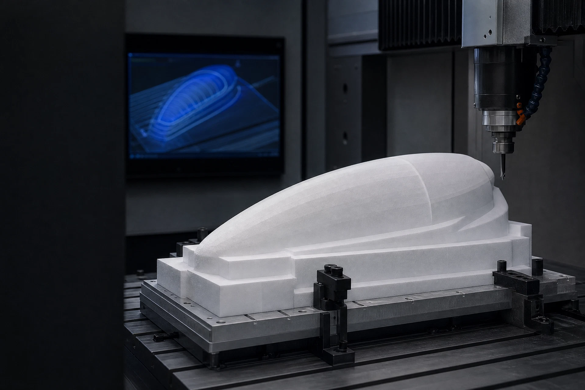
Core geometry from CAD
Contoured and featured foam parts
Tool access and surface review
Project-specific inspection discussion
CAD-to-core workflow
The geometry becomes useful when every handoff has a purpose.
Process mapCAD & revision
Core form
Feature sequence
Inspection
Protected handoff
Drawing-to-core process rail
CAD review
Geometry & toolpath
Core machining
Inspection handoff
Suitable component geometries
The service is relevant for shapes that require 3D profiles, drilled holes, routed channels, grooves, contours, or other details that need a controlled preparation path before composite assembly.
What a technical review considers
A review can consider input format, feature definition, material form, machining sequence, handling, inspection reference, and the technical files needed for an RFQ.
Begin with a production-useful drawing
A machining review becomes more useful when the team receives a stable geometric reference. STEP, STP, STL, DXF, DWG, and PDF drawings can communicate different aspects of the component. The review should identify which file controls the geometry, what dimensions matter, where surfaces interface with other components, and which features are informational versus production-critical.
Sequence the core preparation around the component
CNC milling, routing, drilling, grooving, and contouring are not separate marketing labels; they are possible operations in a chosen preparation sequence. The order can affect how the core is held, how features are accessed, what surface condition is expected, and how the finished core is handled before composite lay-up or assembly.
Surface and dimensional discussion belongs in the RFQ
Where a feature is important to a mating surface, mould, laminate interface, or assembly sequence, it should be identified in the project brief. Inspection references, allowable variation, visible surfaces, and handling requirements are agreed according to the actual part. The website does not assign universal tolerances or surface standards to every foam-core project.
Design the handoff to composite manufacturing
The completed core must arrive in a condition that works with the downstream process. That can include the required geometry, packaging approach, feature protection, part identification, and any agreed inspection information. Connecting machining to this handoff is what keeps the page focused on composite core engineering rather than generic CNC work.
What PMI foam CNC machining is designed to solve
PMI foam CNC machining is a preparation path for moving from a material blank to a core geometry that supports a composite component. It is used when the part requires more than a simple cut outline: a contour, relief, channel, interface, hole pattern, pocket, step or other drawing-defined feature. The machining plan is valuable only when it connects to the laminate, mould, bonding or assembly process that follows.
Read 2D, 3D and curved geometry as different production questions
A 2D outline, drilled pattern and routed channel can be reviewed from drawing references, while a 3D profile or double-curved surface usually benefits from a stable model. The CAD package should communicate the controlling geometry, which faces meet another component, where features transition, and what information is necessary for inspection. This avoids treating a visual model as a complete production instruction.
Use a clear CAD file hierarchy
STEP and STP models can describe complex solids; STL can support form review; DXF and DWG can convey 2D profiles; PDF can carry drawing notes; IGES and ZIP may be useful where project systems use them. The review should establish the controlling revision and identify which files are reference-only. Geometry, notes and inspection intent need to be read together.
Sequence the machining workflow around the foam core
A typical workflow considers CAD review, material and core-form discussion, workholding, rough feature creation, finishing or contouring, dimensional or visual inspection, part identification and packing handoff. The sequence is not a generic machine recipe: it is selected from the real part, access direction, feature sensitivity and downstream composite process.
Treat inspection and surface discussion as part of the drawing review
Where a core will meet a mould, skin, bond line or assembly interface, those features should be identified in the RFQ. Reference dimensions, visible surfaces, measurement expectations and feature protection can then be discussed in a project-specific way. The site deliberately does not publish universal tolerances, feeds, speeds or surface standards for all PMI foam projects.
Common machining risks are prevented upstream
Chipping, local deformation, unclear edge expectations and geometry mismatch are not resolved by a generic operation name. A well-prepared brief identifies the controlling model, material form, critical features, handling conditions, downstream step and inspection reference. This creates an early conversation about how to preserve intended geometry through the full core-to-composite workflow.
Related questions
Questions that make the next engineering conversation more useful.
01Which CAD format is most useful for PMI foam CNC machining?
A 3D model such as STEP or STP is often useful for complex geometry, while DXF, DWG, and PDF can help define 2D features or drawing notes. The best file package depends on the component and should include the dimensional reference needed for review.
02Can machining include contours, grooves and drilled features?
The potential feature set is assessed from the core form, geometry, tooling access, and project requirements. Send the drawing and process context for a project-specific review.
03What is PMI foam CNC machining?
It is a drawing-led core-preparation path that uses selected machining operations to create PMI foam geometry for a composite component. The process is scoped from the part, not from a generic operation list.
04Can a PMI core include 3D contours?
3D contour work can be assessed from a stable model, material form, feature transitions and the intended downstream process. Send the model and component context for a project review.
05Can grooves, channels, holes and pockets be discussed in one RFQ?
Yes. The RFQ should identify the controlling drawing, feature purpose, interfaces, access direction and any inspection requirement so the machining scope is connected to the real part.
06Which CAD files can be submitted?
The intake supports STEP, STP, STL, DXF, DWG, IGES, PDF and ZIP. Include revision context and clarify which file controls the geometry where more than one file is supplied.
07How are dimensional expectations defined?
They should be defined by the drawing, the features that govern component fit and the agreed inspection reference. Universal tolerance claims are not appropriate for every foam-core geometry.
08How can chipping or deformation risk be reduced?
Start with the correct material form, stable geometry reference, feature sequence, workholding discussion and handoff requirements. The relevant approach follows the part and project requirements.
09Does CNC machining include packing and handoff planning?
The RFQ can identify feature protection, part identification, packing and next-process expectations so the prepared core reaches the composite or assembly stage in the required condition.
10How do I request a CNC quote?
Upload the drawing or model, describe the component and process, state any known material or thickness direction, quantity context, critical features, inspection needs and target delivery question.
11How should pmi foam cnc machining be specified?
Start with the component, laminate concept, operating conditions, geometry, and manufacturing route. The applicable material grade and technical data should be confirmed against the specific project.
12Can a drawing be reviewed before a quotation?
Yes. STEP, STP, STL, DXF, DWG, PDF, and ZIP files can be submitted with an RFQ so the team can review the core form, machining scope, and information required for a project-specific response.