
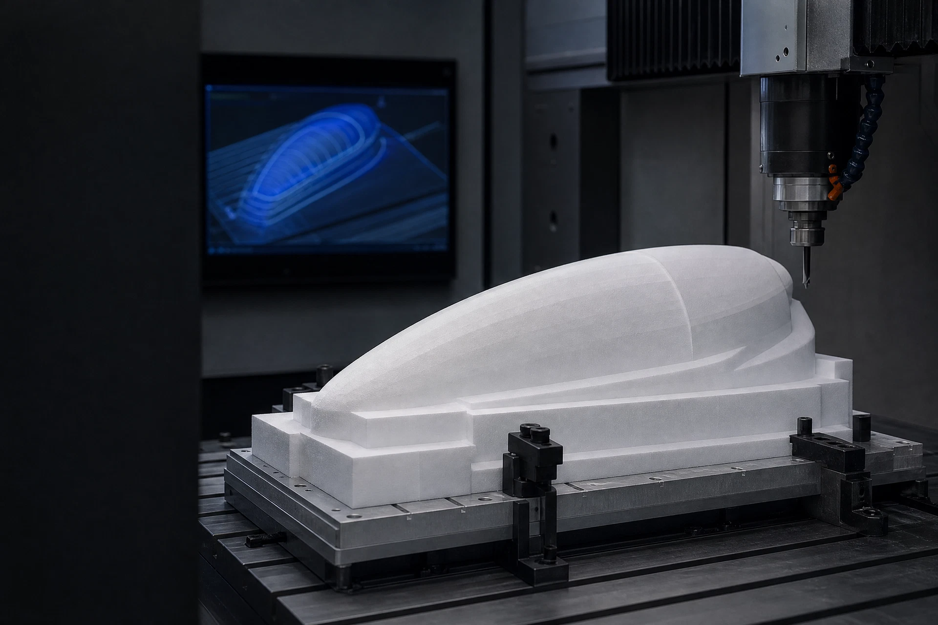
PMI foam core · composite materials · CNC shaping

Case Studies / engineering resource

CNC Machined PMI Foam Core for UAV

This is a Typical Application Case, not a claim about a named customer project. It illustrates the technical questions a similar structure may raise and the workflow used to scope a PMI foam core or CNC-machined core enquiry.

CAD-led core machining process
Typical workflowDrawing / preparation / review
01Project focus

Representative component challenge

02Project focus

Material and geometry questions

03Project focus

CNC and composite workflow

04Project focus

Project-specific RFQ inputs

Engineering record

01

Component context

02

Core & geometry

03

Process & review

01
Engineering note

Typical engineering challenge

The case structure starts with the component objective, its geometry, the required core preparation, and the manufacturing steps that may follow. It does not assert customer, country, test, certification, or project-performance data.

02
Engineering note

Useful project inputs

A drawing, component context, intended processing route, material preference if known, and inspection requirements help convert a typical application into a project-specific technical review.

03
Engineering note

Typical UAV case: map the 3D drawing to a finished core

This Typical Application Case illustrates how a UAV-oriented core enquiry can begin with a 3D model, identify feature preparation needs, and establish a machining-to-composite workflow. It is not a claim about a named aircraft, customer, test result, or flight programme.

Related questions

Questions that make the next engineering conversation more useful.

01How should typical application case be specified?

Start with the component, laminate concept, operating conditions, geometry, and manufacturing route. The applicable material grade and technical data should be confirmed against the specific project.

02Can a drawing be reviewed before a quotation?

Yes. STEP, STP, STL, DXF, DWG, PDF, and ZIP files can be submitted with an RFQ so the team can review the core form, machining scope, and information required for a project-specific response.

Reference Engineering Scenario

UAV-oriented composite structure

This is a reference engineering scenario, not a named customer case. It does not claim a customer, programme, order quantity, test result, certification, project value or measured outcome.

Operator machining a contoured foam core as UAV scenario context
Representative visual context only; project requirements remain subject to the actual drawing and applicable documentation.
01

Engineering challenge

Turn a controlled 3D component model into a prepared lightweight core without assuming an aircraft programme, customer, flight result or qualification.

02

Required geometry

A wing, fairing, fuselage-adjacent or internal core form may require contours, pockets, holes, edge transitions and interfaces defined by CAD.

03

Material considerations

Confirm the applicable PMI grade document, starting form, thickness and project-specific data requirement before release.

04

CNC and composite process

Review CAD, blank preparation, selected machining sequence and the downstream composite handoff.

05

Inspection and packaging

Identify drawing-controlled features, visible surfaces, protection, marking and packing requirements in the RFQ.

Use this scenario as a checklist for a comparable inquiry. The controlled drawing, selected material documentation, process context and inspection requirements define the actual project scope.

Discuss a UAV core drawing