
PMI foam core · composite materials · CNC shaping

PMI Foam / engineering resource

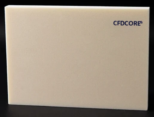
PMI foam sheet as a starting format for engineered core geometry.

PMI foam sheet gives a technical team a clear starting format for flat or subsequently machined core concepts. The relevant sheet, thickness, and preparation route should be matched to the finished component requirements rather than treated as a universal stock specification.

PMI structural foam core product surface
Material evidencePMI foam / core form
01Project focus

Flat PMI sheet format

02Project focus

CNC routing and milling preparation

03Project focus

Component-led thickness discussion

04Project focus

Composite process compatibility review

Catalog / specification frame

01 / Material formCore, sheet, block, or custom geometry
02 / Selection inputsComponent, process, thickness, and geometry
03 / Technical valuesConfirm in the applicable grade datasheet
04 / Next actionProject-specific material and drawing review
01
Engineering note

Sheet format and geometry planning

Flat stock is typically considered when the part geometry will be machined, grooved, drilled, or otherwise prepared before lay-up. CAD input can clarify nesting, features, and the relationship between the blank and finished core.

02
Engineering note

Handling and project documentation

The applicable handling, storage, processing, and packaging requirements should be confirmed with the technical data for the chosen grade and project scope.

Related questions

Questions that make the next engineering conversation more useful.

01How should pmi foam sheet be specified?

Start with the component, laminate concept, operating conditions, geometry, and manufacturing route. The applicable material grade and technical data should be confirmed against the specific project.

02Can a drawing be reviewed before a quotation?

Yes. STEP, STP, STL, DXF, DWG, PDF, and ZIP files can be submitted with an RFQ so the team can review the core form, machining scope, and information required for a project-specific response.
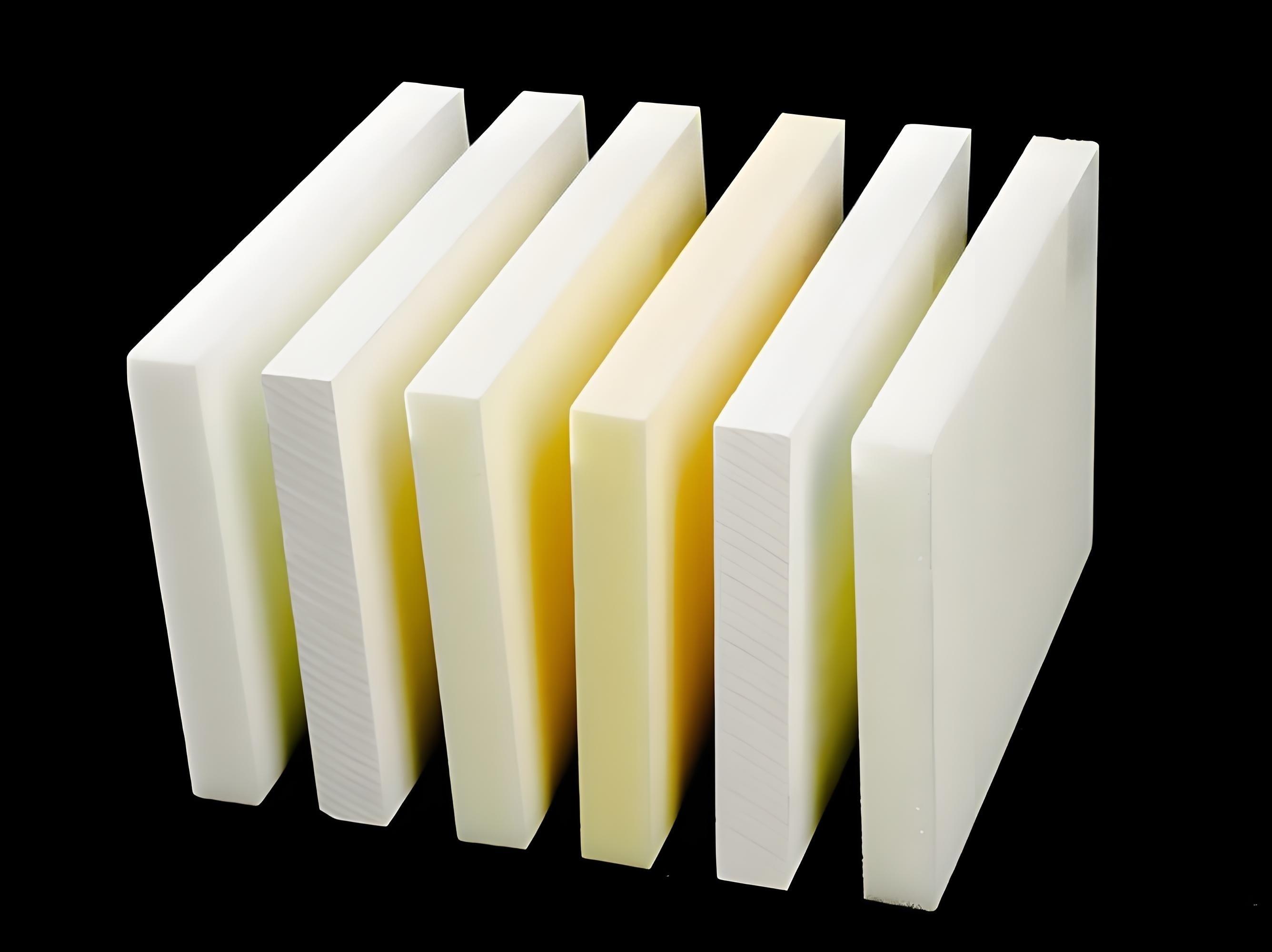
PMI foam sheets and sample forms on a dark background

Sheet-to-core pathway

Use the starting sheet to plan the finished geometry—not to assume the finished part.

A PMI sheet can remain planar or become a machining blank. The drawing, thickness, nesting, feature definition and downstream composite route determine the review. The images below show representative form and CNC context only.

  1. 01Identify the required nominal sheet or blank form
  2. 02Use CAD to distinguish final geometry from machining or nesting allowance
  3. 03Confirm handling, feature protection and the next manufacturing handoff
Discuss a PMI foam sheet request
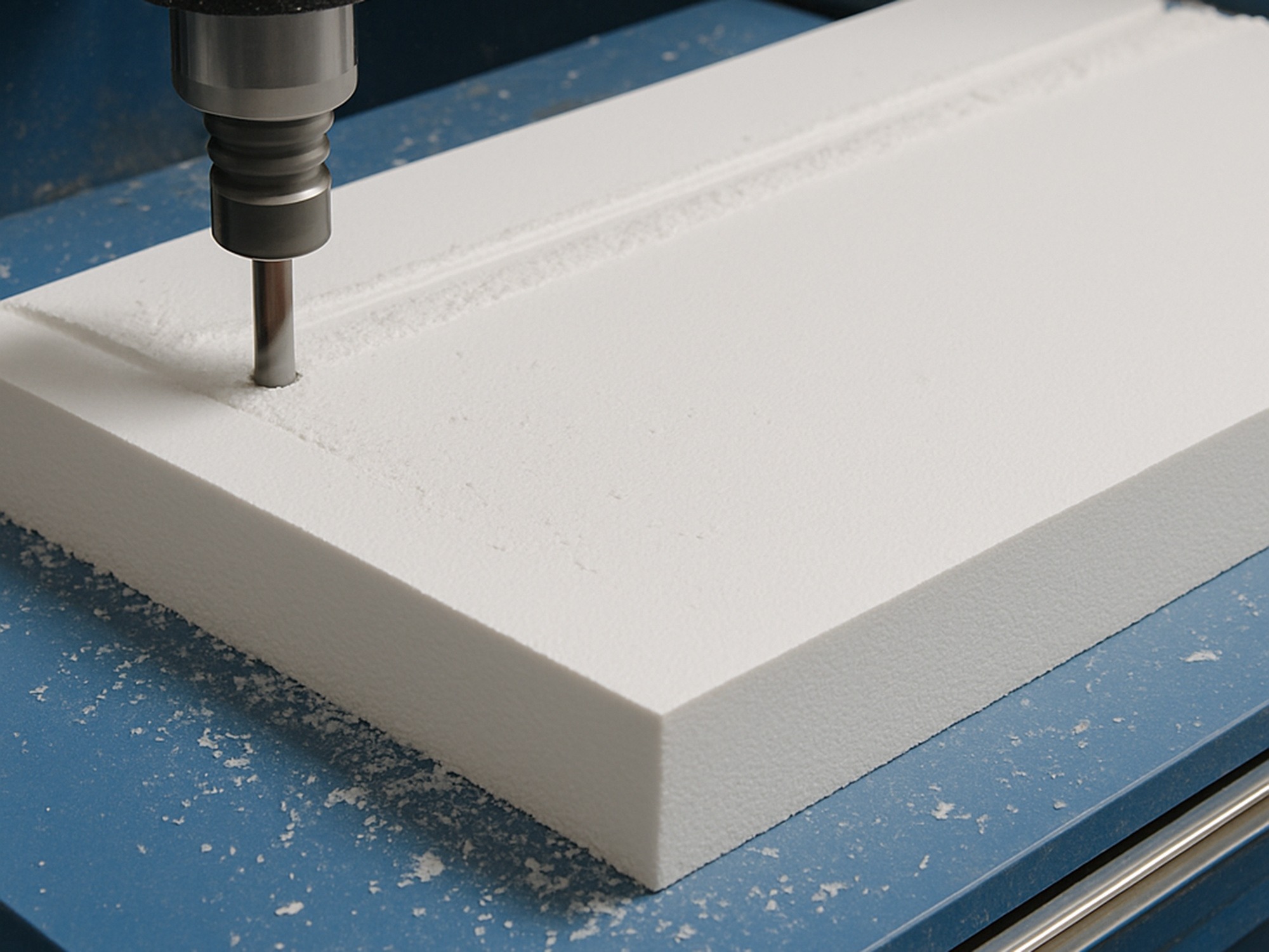
CNC cutter preparing a PMI foam material block

Process and handoff evidence

Drawing-led CNC preparation / feature context. Images are representative project context and do not independently establish a certified process, finished-part result, material availability or named customer case.