
PMI foam core · composite materials · CNC shaping

PMI Foam / engineering resource

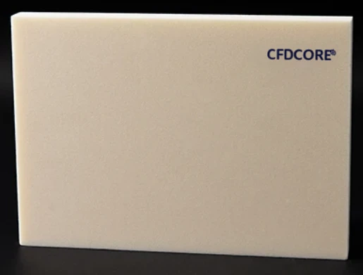
PMI foam block for three-dimensional core concepts.

Block form can be relevant where a project starts with custom 3D geometry rather than a simple planar panel. It gives the technical discussion room to focus on final form, tool access, surface requirements, and the composite process that follows.

PMI structural foam core product surface
Material evidencePMI foam / core form
01Project focus

3D core geometry

02Project focus

CNC machining access

03Project focus

Custom feature planning

04Project focus

Drawing-led review

Catalog / specification frame

01 / Material formCore, sheet, block, or custom geometry
02 / Selection inputsComponent, process, thickness, and geometry
03 / Technical valuesConfirm in the applicable grade datasheet
04 / Next actionProject-specific material and drawing review
01
Engineering note

Complex geometry begins with the part model

A usable CAD model identifies contours, cut-outs, drill paths, local features, and the interface between the foam core and surrounding composite construction.

02
Engineering note

Dimensional review before production

Tolerances, inspection method, packaging, and required surface condition must be specified for the actual part. These items should not be assumed from a generic foam description.

Related questions

Questions that make the next engineering conversation more useful.

01How should pmi foam block be specified?

Start with the component, laminate concept, operating conditions, geometry, and manufacturing route. The applicable material grade and technical data should be confirmed against the specific project.

02Can a drawing be reviewed before a quotation?

Yes. STEP, STP, STL, DXF, DWG, PDF, and ZIP files can be submitted with an RFQ so the team can review the core form, machining scope, and information required for a project-specific response.
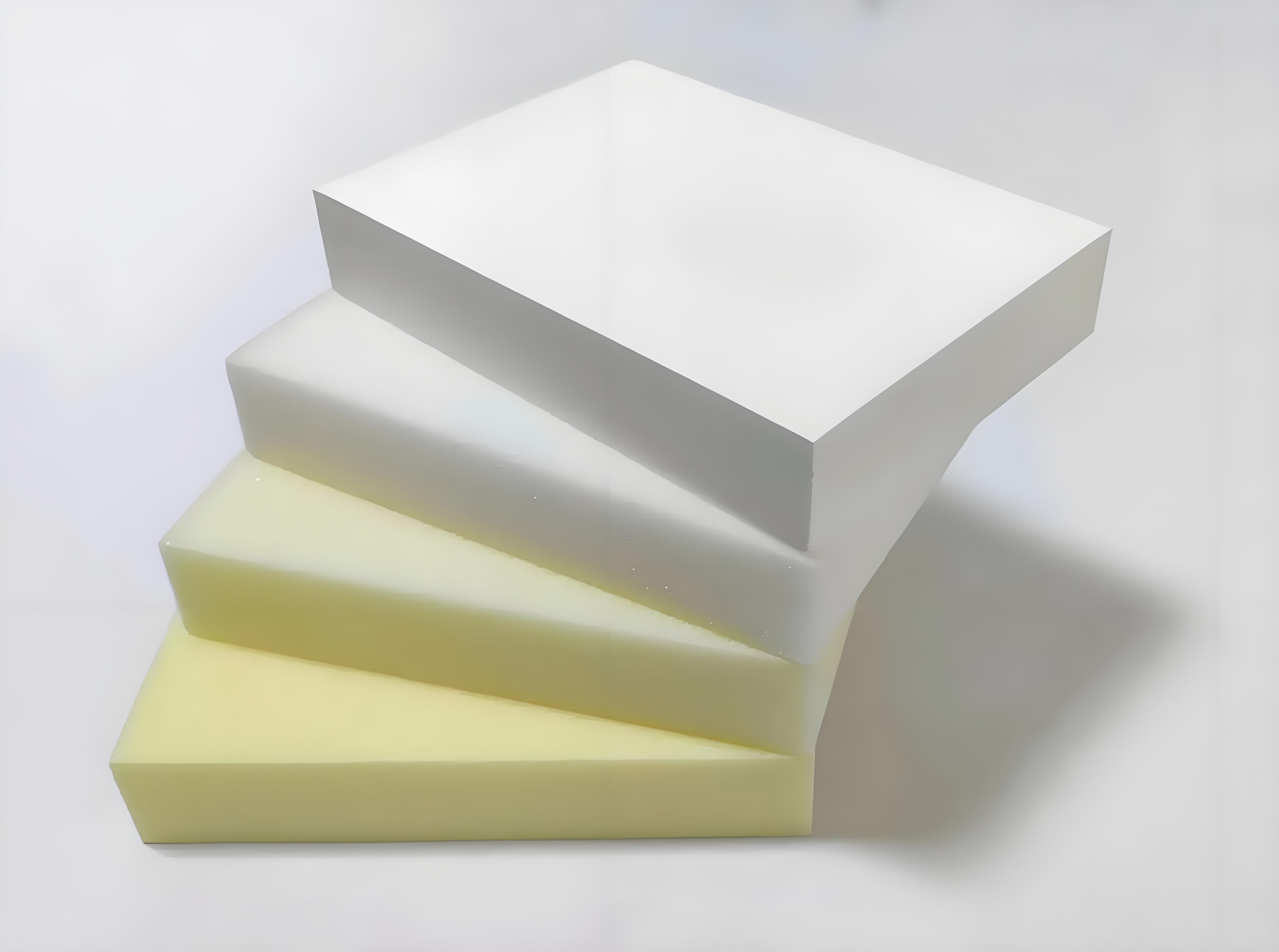

PMI foam blocks in a range of material forms

Block-to-geometry pathway

A block becomes useful when the three-dimensional part is clear.

Block form is evaluated from the 3D envelope, local features, tool access, visible surfaces and composite interfaces. It does not establish a universal machining capability, tolerance or final part outcome without the controlled project file.

  1. 01Establish the controlled model, dimensions and critical interfaces
  2. 02Review blank form, machining access and feature sequence
  3. 03Define inspection references, handling and protective packing for the prepared part
Upload a block-machining drawing
Operator machining a curved foam core on CNC equipment

Process and handoff evidence

Complex geometry / process review context. Images are representative project context and do not independently establish a certified process, finished-part result, material availability or named customer case.