
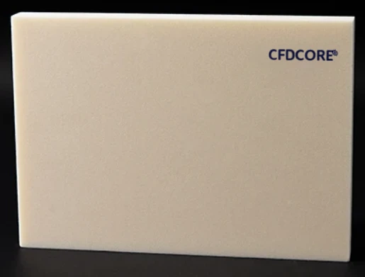
PMI foam core · composite materials · CNC shaping

PMI Foam / engineering resource

CNC machined PMI foam core for geometry that a flat sheet cannot provide.

CNC machined PMI foam core connects a structural foam material choice to a component-ready geometry. It is useful when the core requires controlled contours, drilled features, grooves, local reliefs, or other information contained in a CAD or drawing package.

PMI structural foam core product surface
Material evidencePMI foam / core form
01Project focus

Milling, routing, drilling, and grooving

02Project focus

3D contour and feature preparation

03Project focus

CAD-based machining review

04Project focus

Inspection and packing planning

Catalog / specification frame

01 / Material formCore, sheet, block, or custom geometry
02 / Selection inputsComponent, process, thickness, and geometry
03 / Technical valuesConfirm in the applicable grade datasheet
04 / Next actionProject-specific material and drawing review
01
Engineering note

Why machining is specified

Machining is used to transform core stock into the geometry required for the component. The appropriate strategy depends on the model, tool access, edge conditions, finish expectations, and the manufacturing process that follows.

02
Engineering note

Data and workflow

A typical review examines input files, geometry, machining scope, inspection needs, and packaging. File formats such as STEP, STP, STL, DXF, DWG, and PDF can provide a practical starting point.

Related questions

Questions that make the next engineering conversation more useful.

01How should cnc machined pmi foam core be specified?

Start with the component, laminate concept, operating conditions, geometry, and manufacturing route. The applicable material grade and technical data should be confirmed against the specific project.

02Can a drawing be reviewed before a quotation?

Yes. STEP, STP, STL, DXF, DWG, PDF, and ZIP files can be submitted with an RFQ so the team can review the core form, machining scope, and information required for a project-specific response.
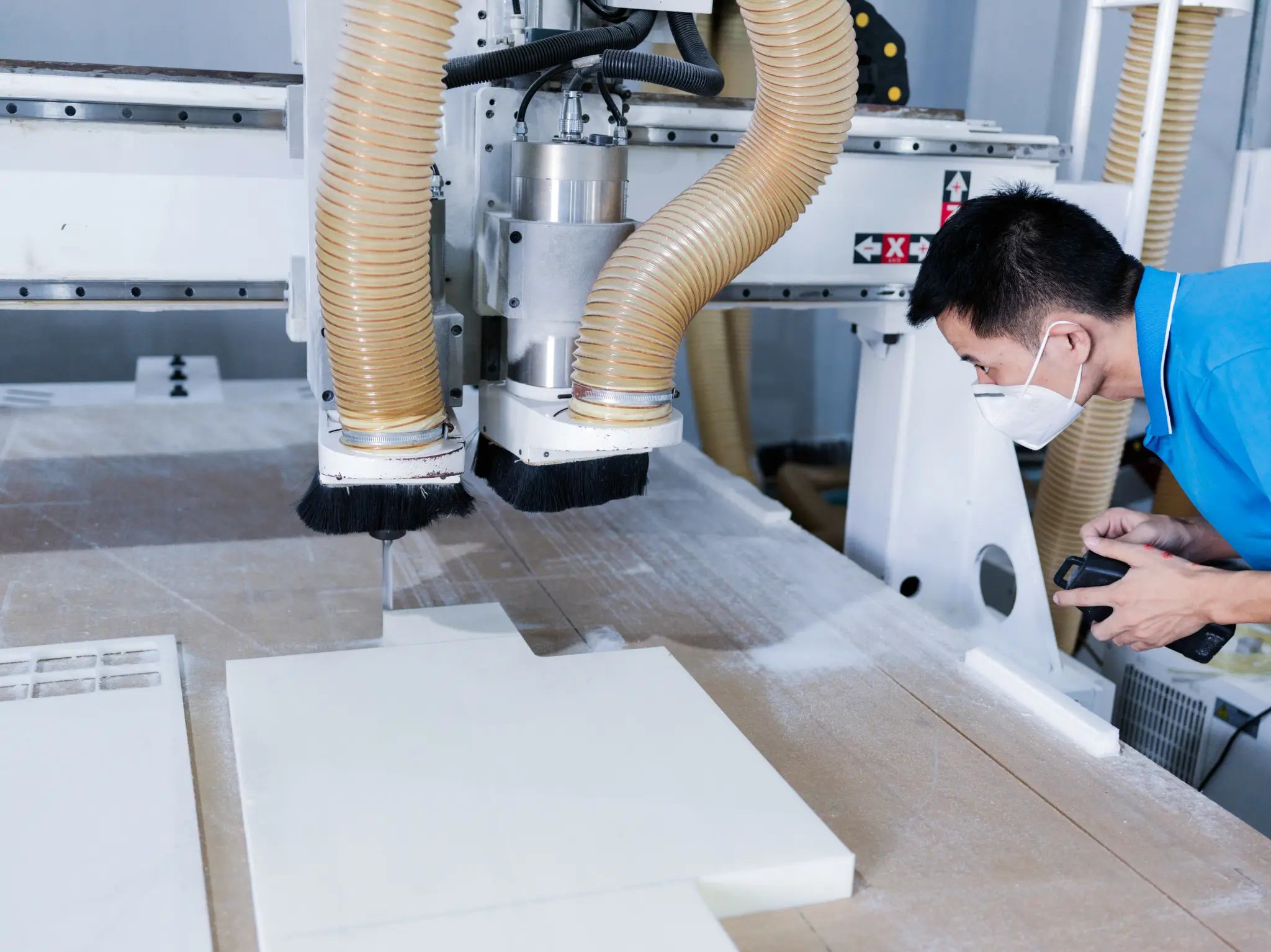
CNC router preparing a PMI foam core with dust extraction

Machined-core workflow

Machining is the bridge between a material blank and a drawing-defined interface.

Milling, routing, drilling, grooving and contouring are selected as part of a drawing-led sequence. The relevant geometry, access, inspection references and downstream process determine the discussion; no universal tolerance or machine result is implied.

  1. 01Confirm CAD, feature purpose and core starting form
  2. 02Plan a feature sequence around access, handling and the downstream component
  3. 03Inspect drawing-controlled surfaces and protect the prepared core for handoff
Request CNC machining review
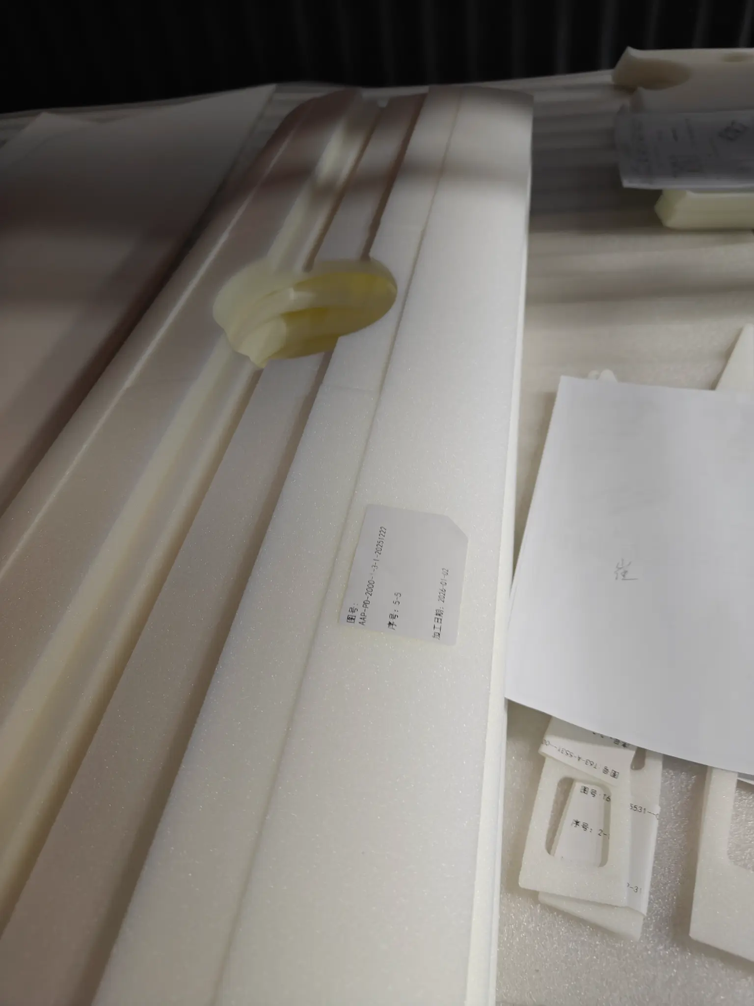
Prepared white PMI foam core components after machining

Process and handoff evidence

Prepared components / geometry and handling context. Images are representative project context and do not independently establish a certified process, finished-part result, material availability or named customer case.