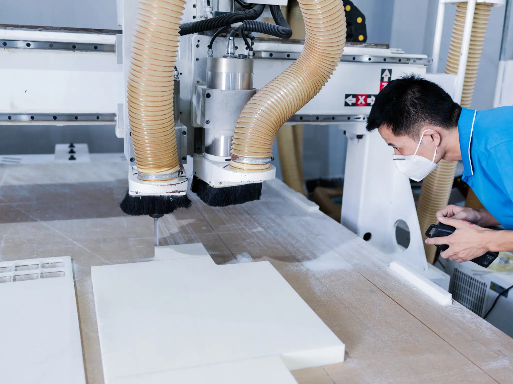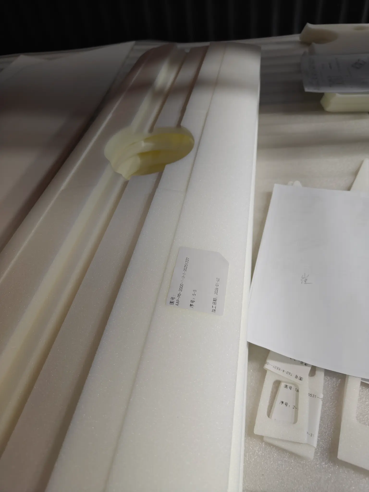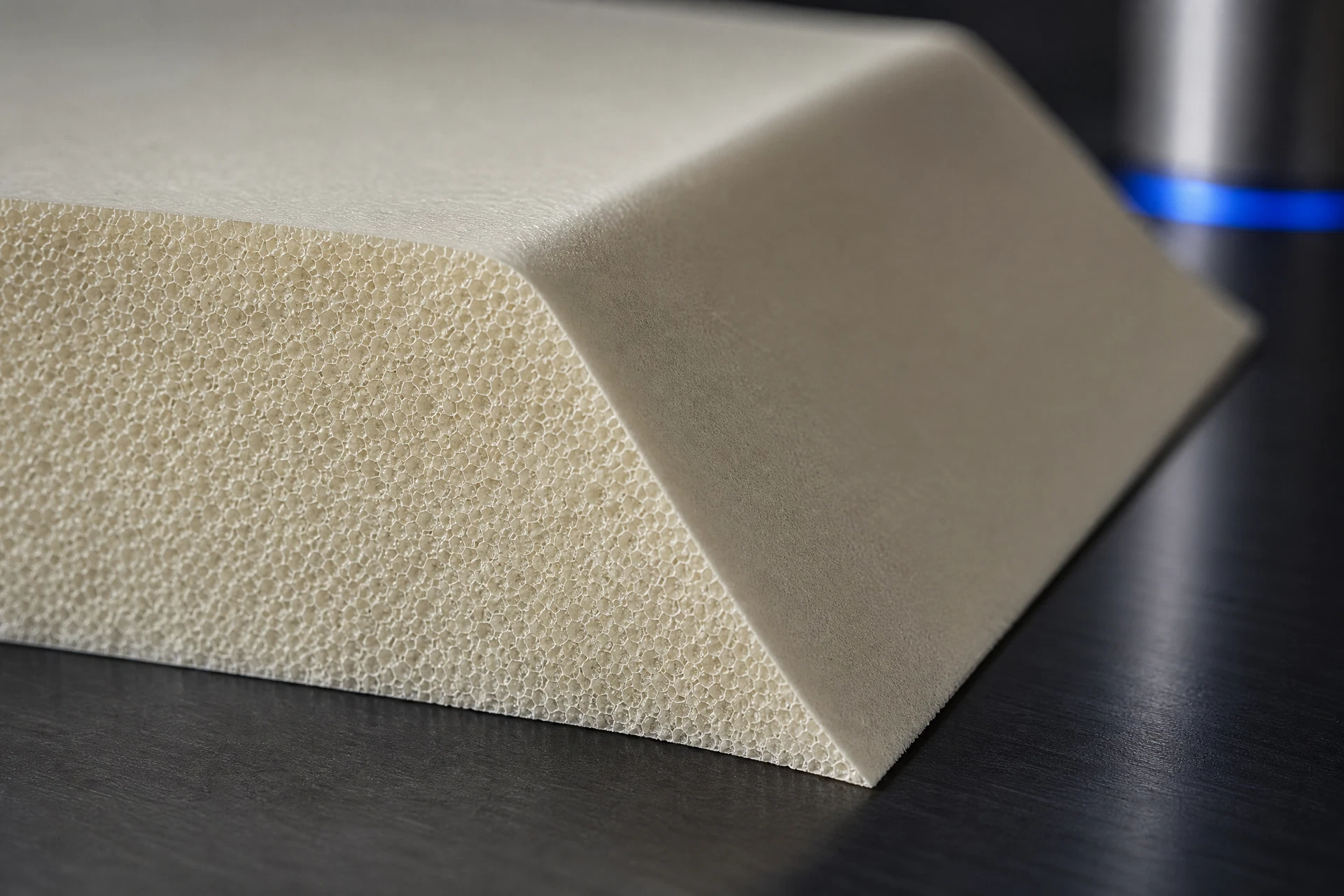
Actual component or application
Geometry, core form, and process
Applicable technical documentation
CAD-led or project-specific RFQ
Engineering record
Component context
Core & geometry
Process & review
Turn the drawing into a controlled machining brief
The useful project discussion begins with the controlling drawing, core form, geometry, intended process, and the questions that require verification. This route is designed to turn those inputs into a traceable engineering or technical-data review rather than a generic material claim.
Confirm the project answer against applicable documentation
Final material selection, technical values, process suitability, inspection scope, commercial availability, and delivery conditions must be confirmed using the relevant grade documentation and the actual project requirements. The page provides a structured starting point, not a universal guarantee.
Related questions
Questions that make the next engineering conversation more useful.
01How should pmi foam cnc machining guide be specified?
Start with the component, laminate concept, operating conditions, geometry, and manufacturing route. The applicable material grade and technical data should be confirmed against the specific project.
02Can a drawing be reviewed before a quotation?
Yes. STEP, STP, STL, DXF, DWG, PDF, and ZIP files can be submitted with an RFQ so the team can review the core form, machining scope, and information required for a project-specific response.