
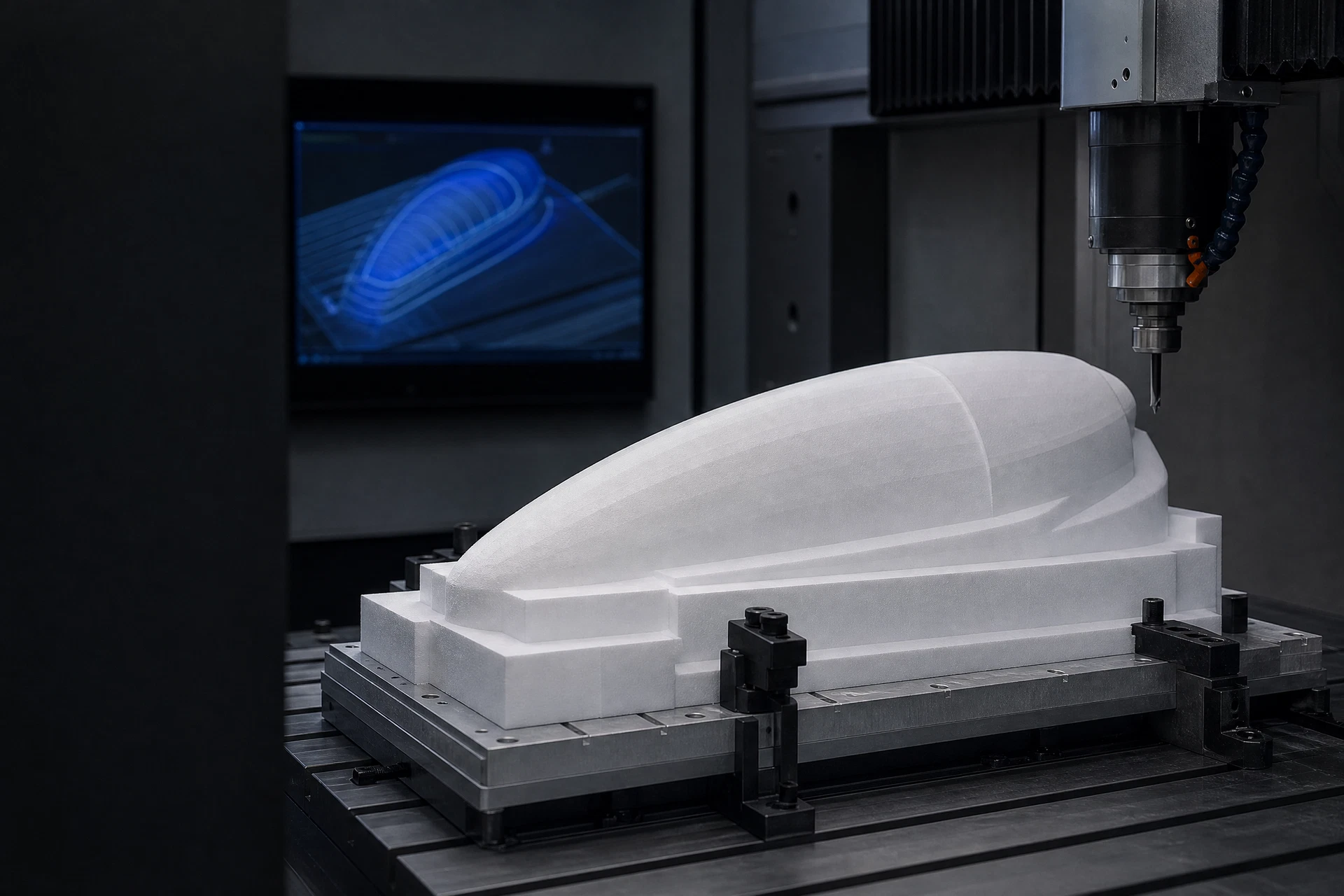
PMI foam and composite-core scope
Suitable geometry and feature review
CAD, inspection, and packing inputs
Project-specific CNC quote
Drawing-to-core process rail
CAD review
Geometry & toolpath
Core machining
Inspection handoff
Define the process from the drawing
The CAD model, drawing notes, feature references, material form, and downstream composite process determine the appropriate preparation approach. Tool selection, cutting strategy, and any tolerance expectation must be reviewed for the real component.
Submit a useful CNC enquiry
Share STEP, STP, STL, DXF, DWG, IGES, PDF, or ZIP files together with the application, material direction if known, thickness, quantity, and any specific inspection or delivery requirement.
Related questions
Questions that make the next engineering conversation more useful.
01How should cnc routing pmi foam be specified?
Start with the component, laminate concept, operating conditions, geometry, and manufacturing route. The applicable material grade and technical data should be confirmed against the specific project.
02Can a drawing be reviewed before a quotation?
Yes. STEP, STP, STL, DXF, DWG, PDF, and ZIP files can be submitted with an RFQ so the team can review the core form, machining scope, and information required for a project-specific response.