
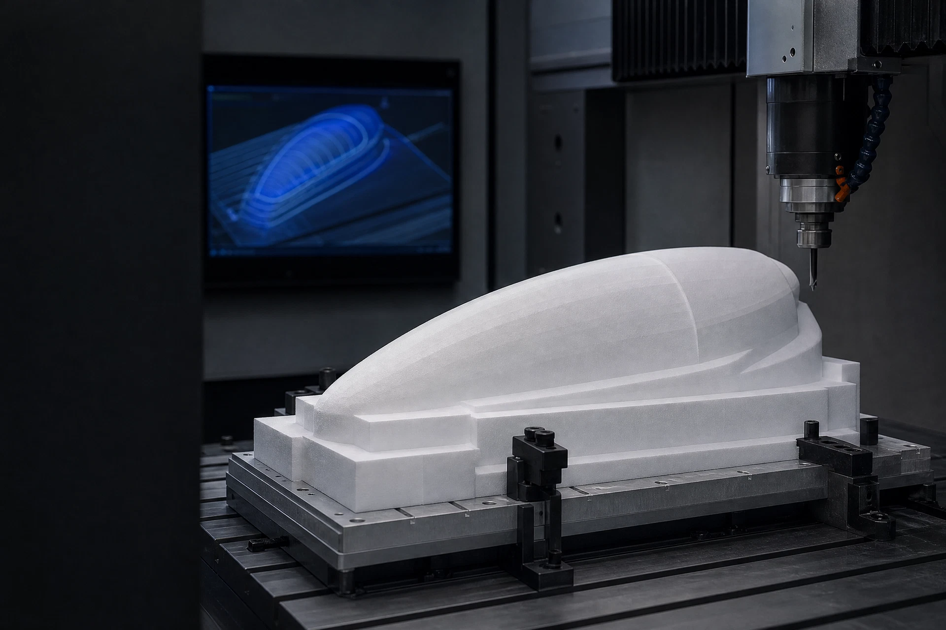
PMI and composite foam context
Drawing-led process definition
Feature and surface review
RFQ with technical files
Drawing-to-core process rail
CAD review
Geometry & toolpath
Core machining
Inspection handoff
Process intent
The process is chosen because the component geometry needs a defined core feature or profile. Tool strategy and sequence are reviewed against the actual material form and part drawing.
Inspection and packing
Required measurements, reference points, visual checks, handling, and packing should be stated for the actual part. The final production plan follows the agreed project scope.
3D machining: continuous contour and complex surface definition
Three-dimensional PMI foam machining addresses profiles that cannot be represented by a flat outline alone. The key input is a stable 3D model plus information about which surfaces, feature transitions, and interfaces are important to the subsequent composite structure.
Related questions
Questions that make the next engineering conversation more useful.
01How should 3d pmi foam machining be specified?
Start with the component, laminate concept, operating conditions, geometry, and manufacturing route. The applicable material grade and technical data should be confirmed against the specific project.
02Can a drawing be reviewed before a quotation?
Yes. STEP, STP, STL, DXF, DWG, PDF, and ZIP files can be submitted with an RFQ so the team can review the core form, machining scope, and information required for a project-specific response.