
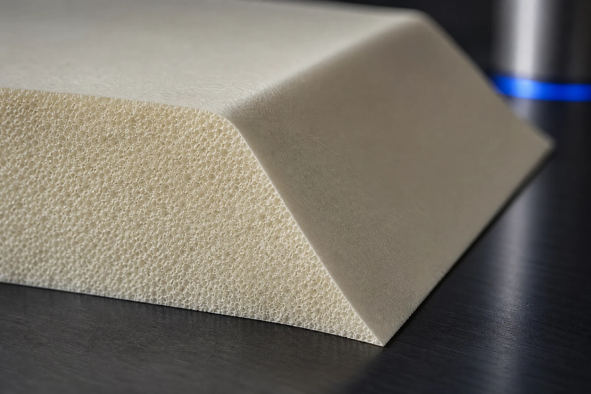
Core thickness inside the sandwich
Face-sheet and interface context
Contour, edge and feature geometry
Project-specific validation
Engineering record
Component context
Core & geometry
Process & review
Read thickness inside the panel architecture
Core thickness creates separation between face sheets and is part of the finished sandwich geometry. It should be considered with the laminate construction, component shape, local load paths, interfaces and the function of the finished panel or shell. A public page cannot choose a thickness without those inputs, but it can help a team identify the data that needs to be reviewed.
Use the drawing to expose local geometry
Steps, transitions, tapered regions, openings, edge details and attachment zones may create different core requirements within one component. A controlled CAD model or drawing should identify nominal thickness, local changes and surfaces that matter to fit or manufacture. That record also helps determine whether a flat blank, block or machined part is the relevant starting form.
Validate the selected thickness with the project
Material data, laminate response, process constraints and inspection requirements must be considered together. The final design decision belongs to the project’s engineering authority and applicable grade documentation, not a generic thickness article.
Related questions
Questions that make the next engineering conversation more useful.
01Can I choose PMI foam thickness from density alone?
No. Thickness must be reviewed with the full sandwich construction, component geometry, process and project requirements.
02Can thickness transitions be CNC machined?
They can be assessed from the CAD model, core form, feature access and the downstream composite workflow.