
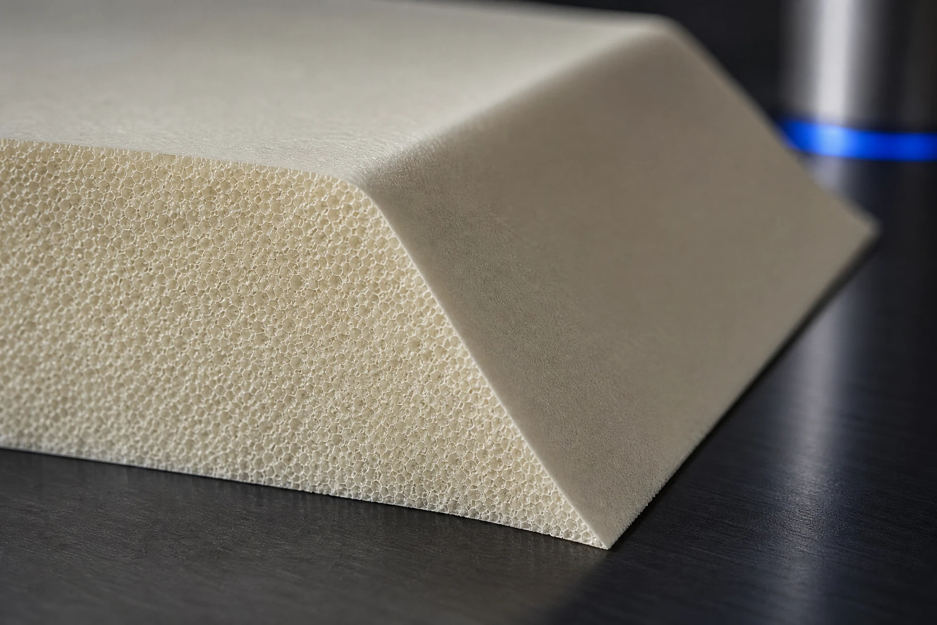
Specific engineering search intent
Drawing and geometry context
Process and handoff review
Controlled technical evidence
Engineering record
Component context
Core & geometry
Process & review
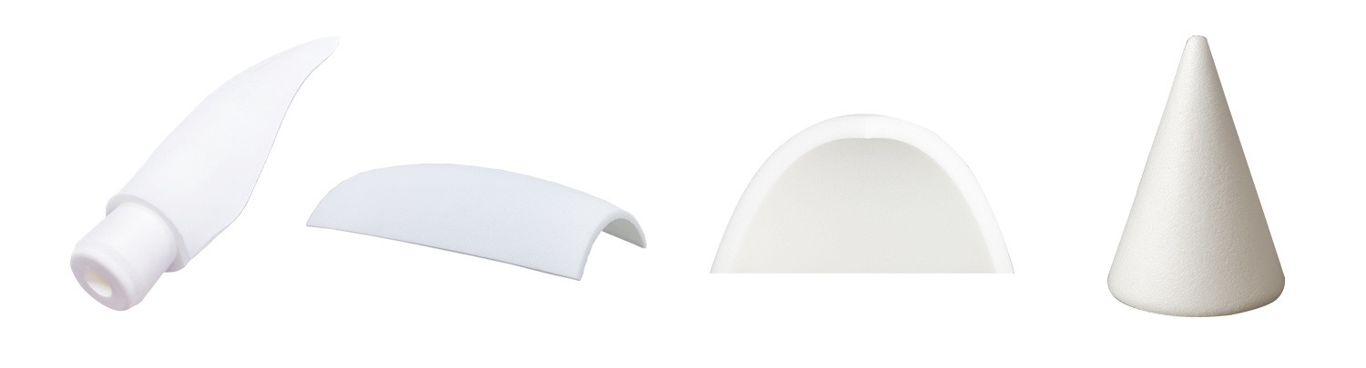
Define the engineering decision
The engineering decision is whether the proposed contour, core architecture, and selected PMI grade are sufficiently defined for the next project review. Consider load paths, interfaces, local transitions, trimming strategy, bond or assembly surfaces, and any areas requiring controlled support or masking. Decisions should be made from the project drawing, CAD model, laminate or assembly context, and applicable grade data—not from generic assumptions. Where inputs are incomplete, record the gap and assign a validation step before releasing CNC preparation.
Translate the part into a controlled geometry brief
Provide the native CAD model or a clearly controlled neutral export together with the latest drawing revision. Identify datums, coordinate systems, split lines, edge conditions, openings, ramps, radii, offsets, machining allowances, and surfaces that must remain untouched. Mark critical interfaces and distinguish finished geometry from stock or sacrificial material. A drawing review should reconcile model-to-drawing intent, orientation, segmentation, and inspection references. Any unresolved geometry should remain an explicit question rather than being inferred during programming.
Connect the material question to the process route
A practical handoff begins with an intake review of CAD, drawings, revision status, material grade, and intended fabrication route. The team can then confirm contour orientation, define machining and inspection references, and identify programming assumptions or missing inputs. Before CNC preparation, document the agreed model version, edge treatment, segmentation, and review owners. After preparation, return the relevant setup or manufacturing information for project approval. Final release should follow the customer’s controlled drawing process and include disposition of open technical questions.
Keep technical evidence within its stated boundary
Applicable grade data, drawing notes, CAD revision history, and project-specific validation results define the evidence boundary for this page. Request the material designation, relevant datasheets, processing guidance, inspection method, and any test plan needed for the intended application. Do not infer performance, certification, environmental behavior, or process capability without supporting documentation. Validation may include a geometry review, representative machined sample, dimensional inspection, bond or assembly trial, and documented engineering sign-off, as appropriate to the project.
Related questions
Questions that make the next engineering conversation more useful.
01What information is needed to review a contoured PMI foam core?
Start with the controlled CAD model, current drawing, material grade or selection basis, interface definition, and intended fabrication context. Include datum requirements, surface restrictions, segmentation preferences, inspection references, and known open questions so the review can distinguish confirmed geometry from assumptions.
02Can CNC preparation begin from a preliminary CAD model?
Preliminary CAD can support an initial feasibility discussion, but CNC preparation should be tied to an agreed revision and documented manufacturing intent. The project team should confirm geometry, allowances, datums, material grade, and inspection criteria before approving programming or downstream fabrication.