
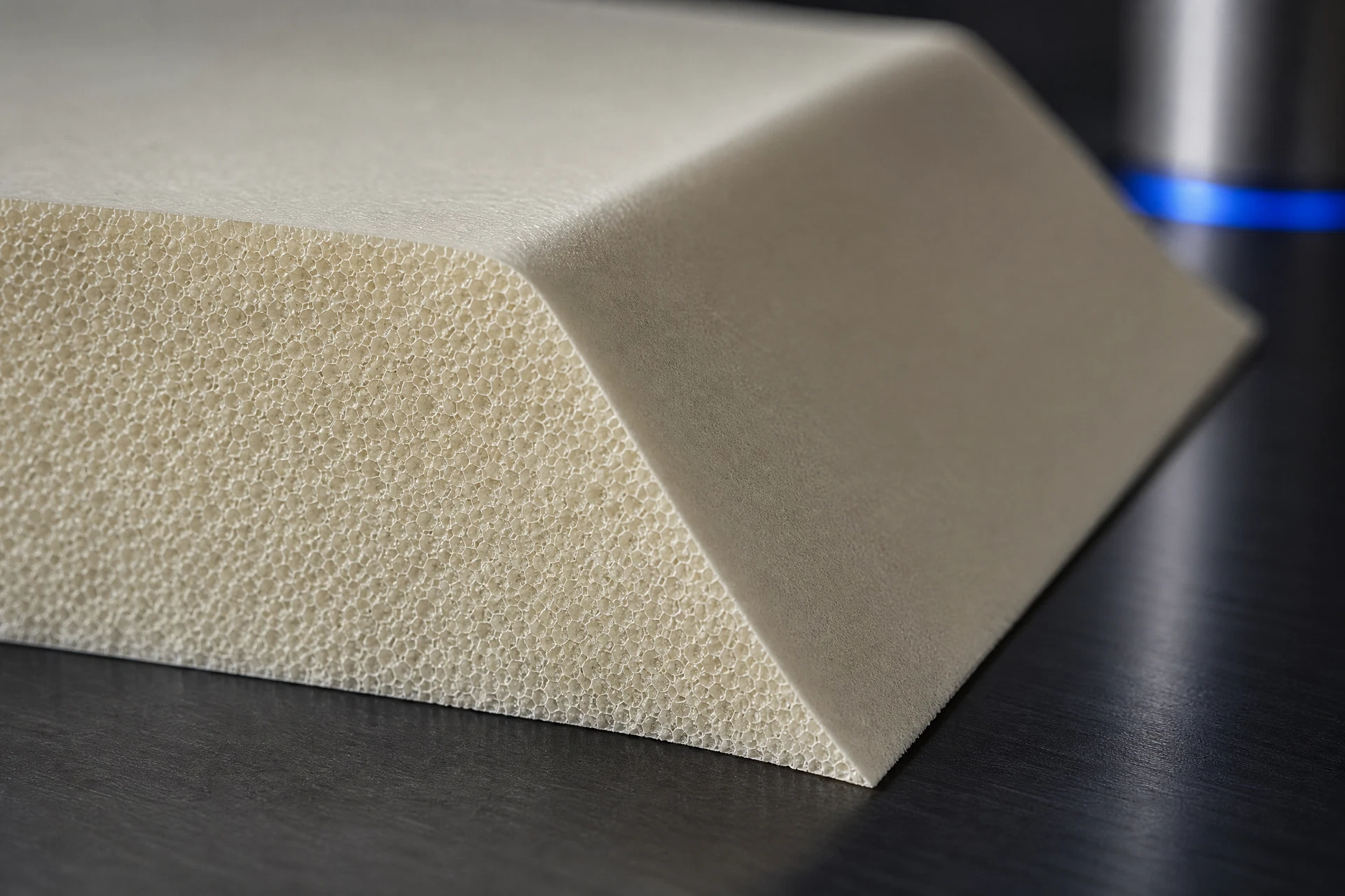
CAD revision and feature definition
Core form and machining access
Inspection reference and handling
Composite-process handoff
Engineering record
Component context
Core & geometry
Process & review
Choose the file that controls the geometry
A STEP or STP model can describe a complex solid, while DXF, DWG and PDF can identify 2D features, notes and inspection references. The first review should establish which file controls production geometry, which revision applies, and whether the 3D model and drawing agree. This avoids creating a CNC path from a visual reference that omits functional requirements.
Sequence features around the core and the next process
Outlines, pockets, grooves, drilled patterns, contours and local transitions may require different access directions and handling assumptions. The machining route should consider core form, workholding, critical surfaces and the downstream laminate or assembly operation. A feature list alone is not a complete process plan; its purpose and reference surfaces need to be stated.
Inspect against the part intent
Identify the dimensions, interfaces and visible surfaces that govern component fit. Packing, part identification and feature protection can then be organized around the actual handoff. Universal tolerance or surface claims are avoided because the appropriate standard depends on the drawing and project requirements.
Related questions
Questions that make the next engineering conversation more useful.
01Which CAD files can be sent for PMI foam CNC review?
STEP, STP, STL, DXF, DWG, IGES, PDF and ZIP can be useful when the controlling revision and feature references are made clear.
02Can grooves, holes and 3D contours be reviewed together?
Yes. Submit the model or drawing with feature purpose, critical interfaces, process context and inspection expectations.