
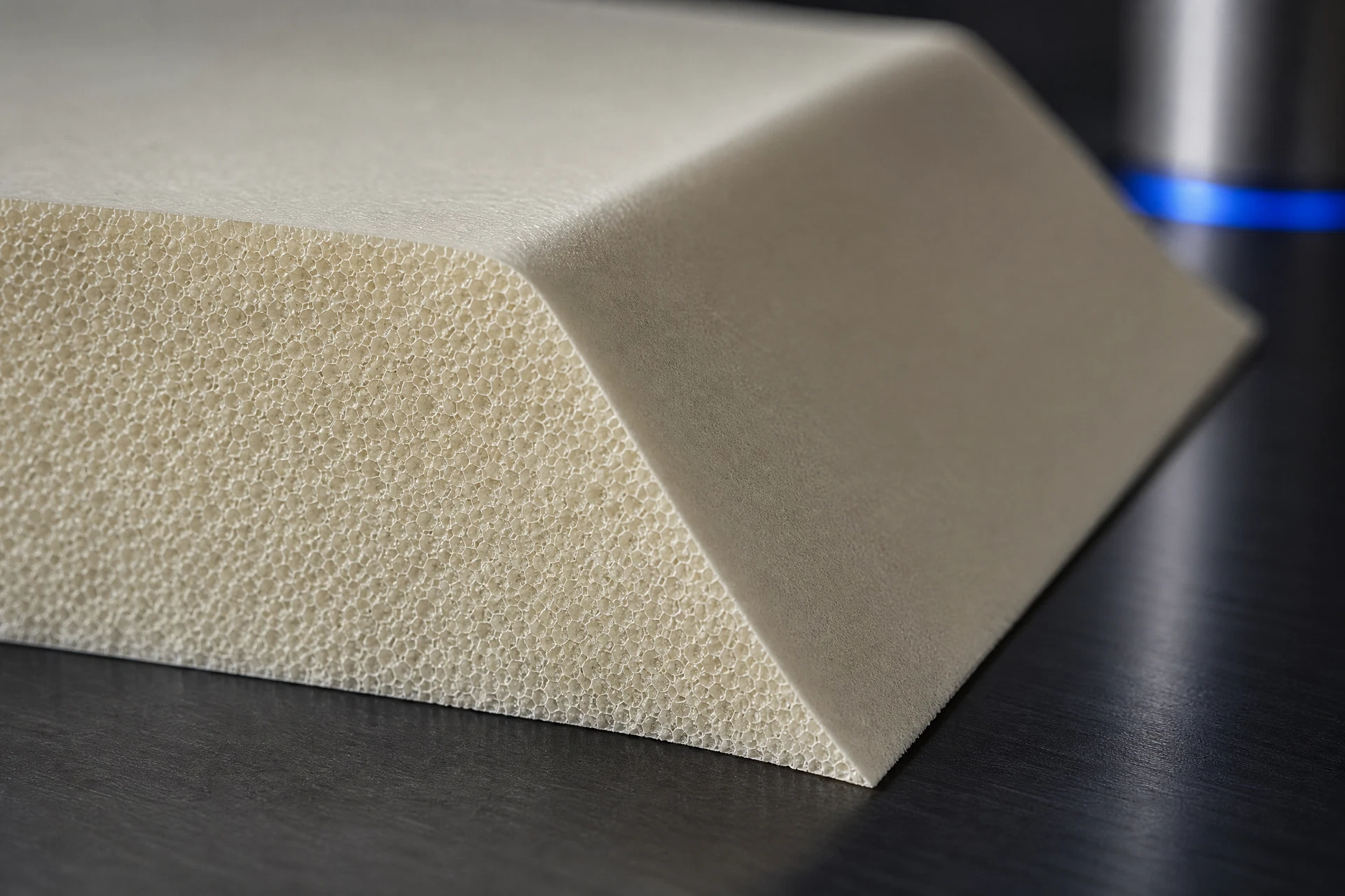
Specific engineering search intent
Drawing and geometry context
Process and handoff review
Controlled technical evidence
Engineering record
Component context
Core & geometry
Process & review

Define the engineering decision
The joining approach should be selected after clarifying what the joint must accomplish in the assembly: connect core segments, support a local transition, preserve a surface condition, or coordinate with skins, inserts, or adjacent components. Reviewers should compare candidate joint concepts against access, fit-up, preparation, handling, cure or set sequence, rework implications, and inspection visibility. No single configuration should be assumed suitable across projects. The decision record should identify assumptions, required inputs, open risks, and the validation activities needed before release.
Translate the part into a controlled geometry brief
A useful drawing package defines the joint envelope, mating surfaces, orientation, part interfaces, edge conditions, gaps or steps, and any features that influence assembly access. Show datum references, section views, material callouts, joining regions, and the intended relationship between foam core, skins, inserts, or closure details. Avoid relying on a nominal sketch alone; the review needs enough geometry to understand contact, sequencing, tooling, and inspection. Project drawings and controlled revisions govern the final interpretation, including any specified fit or tolerance requirements.
Connect the material question to the process route
The process handoff should connect design intent to a controlled assembly sequence. Identify material identities and applicable grades, surface preparation responsibilities, adhesive or joining-system definition where relevant, placement order, fixturing, environmental controls, handling limits, cure or set instructions, and inspection points. The handoff should also state who owns each operation and what records are required. CoreMatrix Materials can support an input review, but the project team must approve the process specification, work instructions, change controls, and acceptance criteria.
Keep technical evidence within its stated boundary
Evidence should be requested in relation to the actual joint design and proposed process, not inferred from the foam name alone. Relevant inputs may include technical data for the specified grade, compatibility information supplied for the joining system, process instructions, drawing revisions, sample-build observations, inspection records, and project-defined test results. The evidence boundary is deliberate: this page does not establish performance, certification, chemical behavior, RF behavior, or production readiness. Those conclusions require documented, configuration-specific review and validation.
Related questions
Questions that make the next engineering conversation more useful.
01What information is needed to review a PMI foam core joint?
Provide the latest drawings or marked-up sections, joint purpose, material and grade designations, mating components, assembly sequence, joining-system intent, access constraints, inspection plan, and project acceptance criteria. A review can then identify missing inputs and validation needs without assuming unverified suitability.
02Can a standard joint detail be used for every PMI foam core assembly?
No. Joint geometry depends on interfaces, loads, access, surface conditions, sequencing, and inspection requirements. A reference detail may support concept development, but the project team must confirm the configuration through controlled drawings, applicable data, process definition, and validation evidence.