
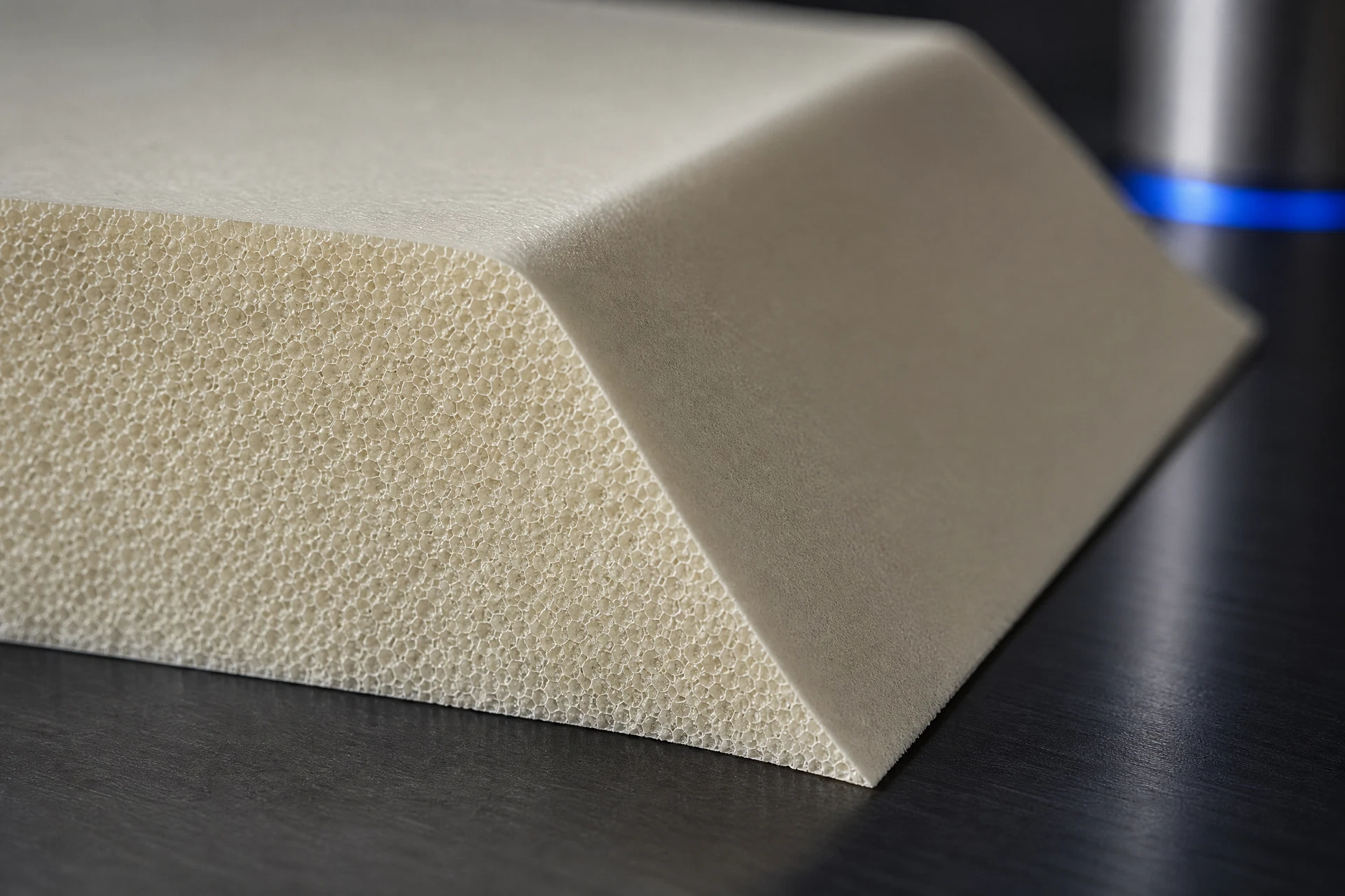
Specific engineering search intent
Drawing and geometry context
Process and handoff review
Controlled technical evidence
Engineering record
Component context
Core & geometry
Process & review
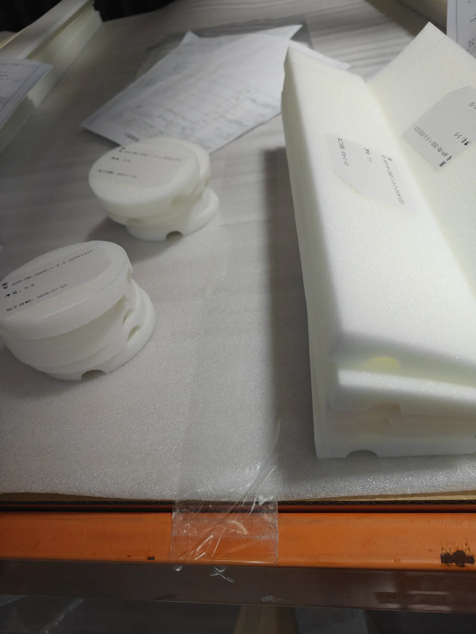
Define the engineering decision
The engineering decision is whether the STL can serve as a usable geometric reference for the requested PMI foam core, or whether a controlled drawing, native CAD model, or clarification is required. Review considers mesh completeness, surface continuity, scale, coordinate orientation, openings, edge conditions, and the relationship between nominal geometry and inspection intent. No fixed tolerance, material performance, RF, chemical, or certification conclusion is assumed from the mesh alone. Acceptance criteria remain tied to approved project documents and recorded decisions.
Translate the part into a controlled geometry brief
Geometry review checks the STL for watertightness, visible gaps, non-manifold regions, inverted or inconsistent normals, faceted surfaces, unexpected shells, and scale or unit ambiguity. Important features should be cross-referenced to controlled dimensions, datums, sections, and revision-controlled drawings where available. The team records which surfaces are manufacturing-defining, which are reference-only, and which require customer confirmation. Where the mesh cannot establish an inspection method or feature requirement, the open question is preserved rather than inferred.
Connect the material question to the process route
The handoff begins with file intake, revision capture, and a comparison of the STL against available drawings, CAD exports, notes, and purchase requirements. Review findings are organized into clarifications, manufacturability considerations, inspection references, and approval gates. After scope alignment, the approved geometry and process assumptions guide machining planning, workholding discussion, finishing requirements, and inspection preparation. RFQ communication identifies included files, exclusions, open decisions, and the evidence expected at each project milestone.
Keep technical evidence within its stated boundary
Project evidence may include the received-file register, mesh review observations, revision history, marked-up screenshots or sections, clarification responses, approved drawing references, inspection records, and final handoff documentation. These records show what was reviewed and which requirements were verified for the specific project; they do not establish universal material behavior, design suitability, or compliance beyond the supplied scope. Any measurement method, sampling approach, or acceptance decision must be defined by the approved project documentation.
Related questions
Questions that make the next engineering conversation more useful.
01Can an STL file alone define PMI foam core machining requirements?
Usually, an STL is strongest as a geometric reference. Production requirements may still require controlled drawings, datum and inspection intent, revision information, material direction, edge conditions, or other project notes. CoreMatrix Materials records gaps and seeks approval rather than inferring requirements from the mesh.
02How does CoreMatrix Materials validate an STL before an RFQ?
The review captures file identity and revision, checks mesh integrity and scale, compares available references, flags manufacturability and inspection questions, and documents assumptions or exclusions. The RFQ can then distinguish approved requirements from unresolved items requiring project confirmation.