
Specific engineering search intent
Drawing and geometry context
Process and handoff review
Controlled technical evidence
Engineering record
Component context
Core & geometry
Process & review
Define the engineering decision
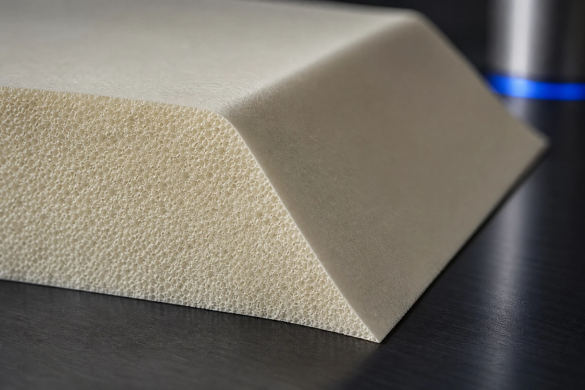
The engineering decision is whether the proposed foam core geometry, reference system, and documentation provide a clear basis for controlled shaping and verification. Review considers feature accessibility, thin or unsupported regions, split lines, machining allowances, datum transfer, surface definitions, and any areas requiring manual finishing or additional inspection. Decisions are recorded against the current drawing and CAD revision, with open questions identified before release. No fixed tolerance, equipment specification, capacity, or delivery assumption is applied without project-specific evidence and agreement.
Translate the part into a controlled geometry brief
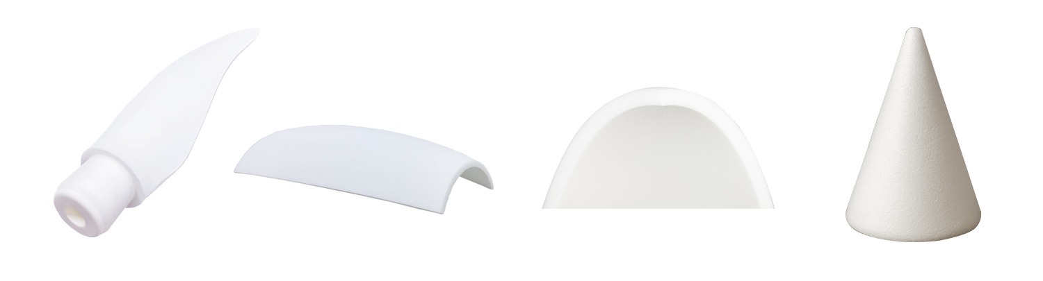
Geometry review establishes what must be shaped, what remains stock, and how the part is referenced during programming and inspection. Useful inputs may include native CAD, neutral models, two-dimensional drawings, sections, marked-up views, material details, coordinate systems, surface requirements, and revision history. The review distinguishes design surfaces from setup or trimming references and identifies ambiguous edges, blends, holes, pockets, offsets, and interface features. Where geometry is incomplete or contradictory, clarification is required before the controlled definition can move into process planning.
Connect the material question to the process route
The process and handoff sequence links design review to a controlled manufacturing package. After files and revisions are checked, the team documents the intended setup logic, machining or trimming approach, support strategy, allowance treatment, and inspection checkpoints appropriate to the geometry. Questions, assumptions, and changes remain visible through revision-controlled communication. Handoff materials can include approved CAD, drawing references, process notes, inspection requirements, and validation records. The resulting RFQ scope describes the work to be reviewed and verified without promising unconfirmed production conditions.
Keep technical evidence within its stated boundary
Evidence is limited to the information available for the specific project: supplied CAD and drawings, revision identifiers, review notes, process decisions, inspection observations, measurement records, and agreed validation outputs. These records support traceability between design intent, shaped geometry, and acceptance review, but they do not establish universal performance claims. Foam behavior, surface condition, dimensional results, downstream fit, and application suitability require project-specific evaluation. Any material, chemical, RF, structural, or certification conclusion must be separately defined, substantiated, and approved by the responsible engineering authority.
Related questions
Questions that make the next engineering conversation more useful.
01What files are needed to review a CNC foam core shaping request?
Provide the current CAD model, applicable drawings, material information, datum or coordinate references, required surfaces, revision history, and any inspection or downstream interface criteria. Sections, marked-up views, and known allowances are helpful when the geometry or handoff intent is not fully defined.
02How are foam core geometry and revision changes controlled?
The review identifies the active CAD and drawing revisions, records assumptions and open questions, and links process and inspection notes to that definition. Changes are evaluated for their effect on geometry, setup, verification, and RFQ scope before the updated package is released.